TS5000DMP-DCX-Series-USER-GUIDE.pdf - 第8页
8 7. DETERMINING DISPENSING OUTPUT A. DC Motor Voltage Level: Voltage controls the motor speed (RPM). Incr eased voltage produces increased motor speed and decreased voltage produces decreased motor speed. B. Motor Shaft…
6
5. SET-UP INSTRUCTIONS
Mechanical Mounting:
Normally, the TS5000DMP-DCX Series valve is used on an automated XYZ table,
with full motion control in the three planes. It is very important that the valve is
mounted on the Z-axis gantry, in a secure manner, that will not allow loosening
during dispense operation. The Z-axis must move in a precise and repeatable
motion for successful dispensing.
The provided mounting bracket, or customer supplied bracket, must be attached to
the Z-axis in a manner that will provide the valve perpendicular travel to the
horizontal plane of the surface on which the fluid will be dispensed. The mounting
should provide a means of accurately adjusting the distance between the dispense
tip and the substrate surface such as a touchdown sensing device or a fixed
distance standoff.
Air Connection:
Filtered air supply must be precisely regulated and should be set between 1-20 psi
(0.07 to 1.38bar). The air supply is not used as the main dispensing force. It is only
required to move fluid to the feed screw chamber.
Electrical Connection:
The TS5000DMP-DCX Series valve requires an electrical connection of two wires
for the DC motor. The motor lead wires are 24
'' (609.60mm) in length. The black
lead wire should be connected to the negative or neutral lead from the motor
control voltage source. To verify the connection, check the rotation direction of
the feed screw. When correctly connected, a positive voltage signal will drive the
feed screw in a counter clockwise direction when view from the dispense tip end.
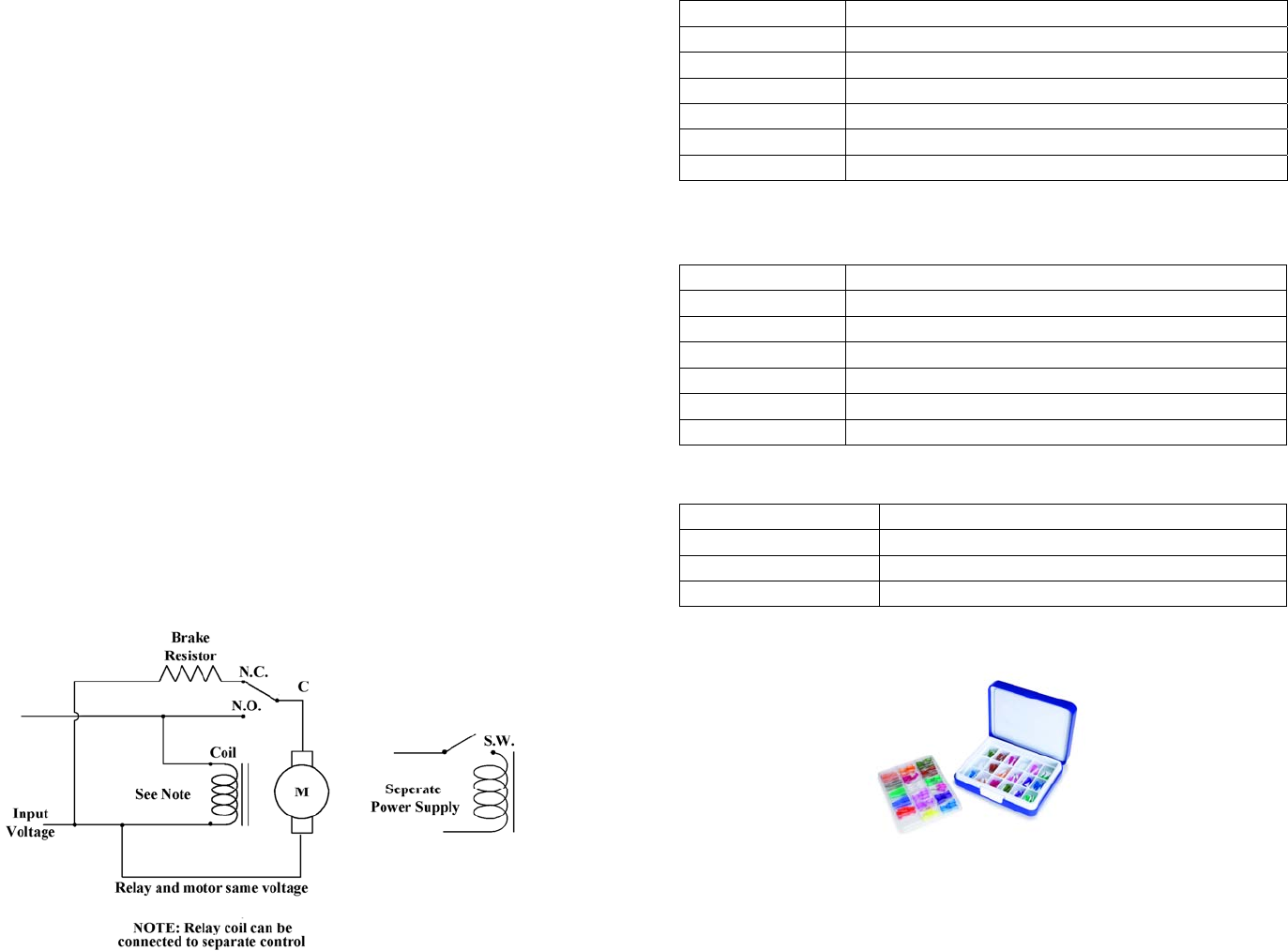
The recommended controller for the TS5000DMP-DCX Series valve is the
TS500R. If another controller is used make sure the control voltage signal is
precisely controlled. The signal should be from a regulated power supply and
should be shunted to positive motor stop. Below is a diagram of a simple braking
circuit:
Figure 2.0
11
10.
DMP INSERT OPTIONS
11.
STANDARD ACCESSORIES
11.1 OPTIONAL ACCESSORIES
PART NUMBER DESCRIPTION
DMP6-10 6 Pitch DMP Assembly, Fixed Red Collar, 10 per pack
DMP6R-10 6 Pitch DMP Assembly, Rotating Red Collar, 10 per pack
DMP8-10 8 Pitch DMP Assembly, Fixed Black Collar, 10 per pack
DMP8R-10 8 Pitch DMP Assembly, Rotating Black Collar, 10 per pack
DMP16-10 16 Pitch DMP Assembly, Fixed Blue Collar, 10 per pack
DMP16R-10 16 Pitch DMP Assembly, Rotating Blue Collar, 10 per pack
PART NUMBER DESCRIPTION
5000-000-005 Valve Mounting Bracket
5000-015-000 TS-SS Sample Tip Kit
TS3706 Syringe Bracket Kit
TSD1135-18 6 Pin DIN Socket
71003RHB 10cc Receiver Head, 3ft (0.9M)
73003RHB 30cc Receiver Head, 3ft (0.9M)
PART NUMBER DESCRIPTION
TN00DKIT Complete Dispensing Tip Kit
9000-000-112 Sample Tip Kit
5000-000-082 TS-SS Tip Torque Tool
10
9.
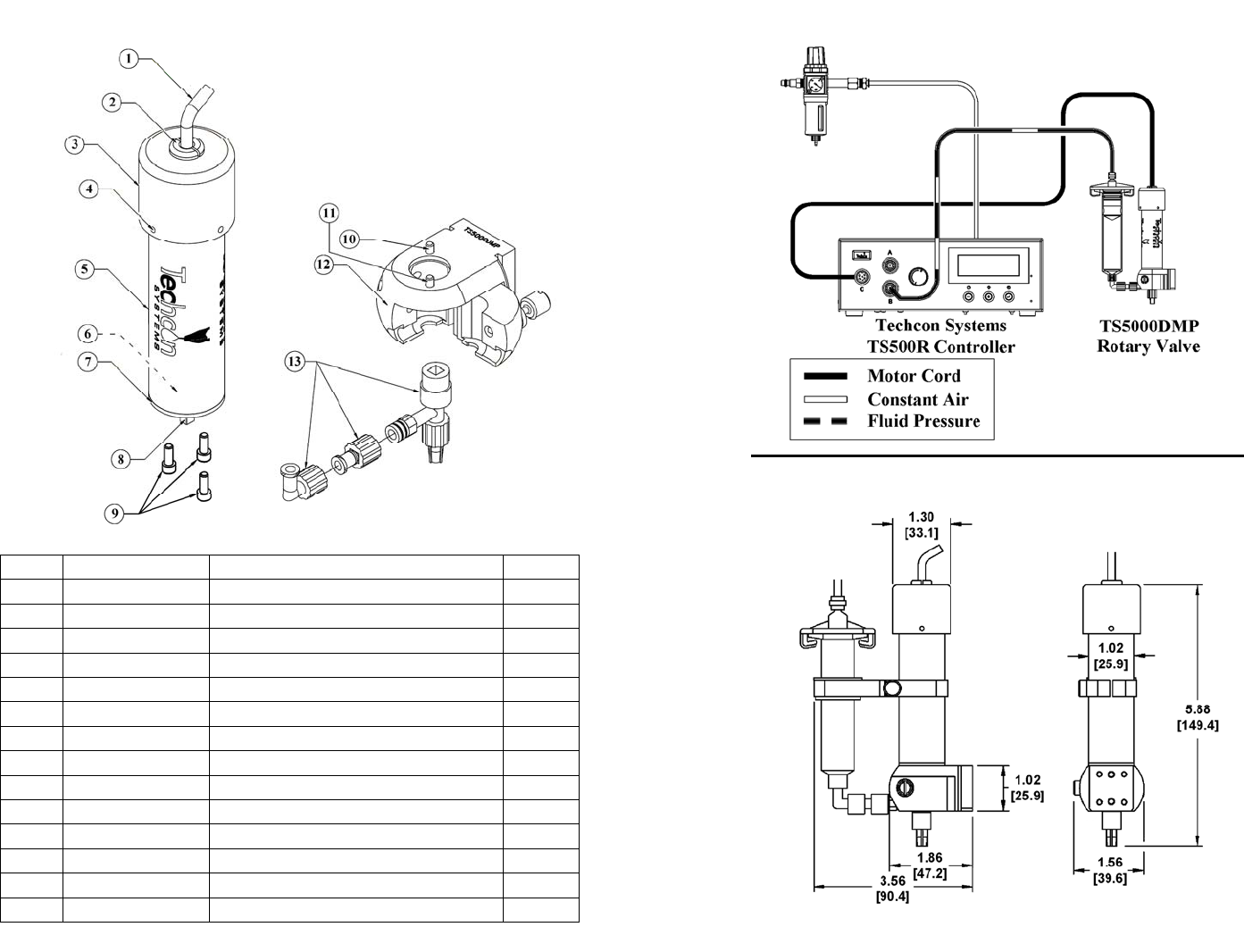
SPARE PARTS
ITEM PART NUMBER DESCRIPTION QTY
1 TSD1415-12 Cable 1
2 TSD1401-7 Bushing 1
3 5000-000-171 Sleeve Cap 1
4 TSD1103-334 Cap Screw 4
5 5000-000-346 Motor Sleeve 1
6 TSD1412-61 Motor 1
7 T1000295 Motor Mounting Plate 1
8 2200-000-011 Square Drive 1
9 TSD1103-330 Mounting Plate Screws 3
10 TSD1103-14 Body Screw, Long 1
11 TSD1103-10 Body Screw, Short 1
12 A0100167 Body For TS5000DMP-DCX 1
12* A0100184 Body For TS5000DMP-DCXL 1
13
See Section 10
DMP Insert 1
NOTE: When replacing the motor (6)
and square drive (8), Loctite #86 AVV
must be used, to bond the square drive
to the motor shaft. The square drive
must be flush with the end of the motor
shaft and any visible excess must be
cleaned off.
Figure 5.0
7
6. TYPICAL SYSTEM SET-UP
Figure 4.0
Dimensions are in
inches (mm)
Figure 3.0
Figure 3.0
8
7. DETERMINING DISPENSING OUTPUT
A. DC Motor Voltage Level:
Voltage controls the motor speed (RPM). Increased voltage produces increased
motor speed and decreased voltage produces decreased motor speed.
B. Motor Shaft Speed:
Motor gear ratio configuration determines final shaft speed. High RPM = High
Output. Low RPM = Low Output.
C. Feed Screw Pitch:
Rate of fluid dispensed is determined by the pitch of the feed screw. A high pitch
number will produce a low dispense rate and a low pitch number will produce a
higher dispense rate. A high pitch number will provide improved accuracy than a
low pitch number.
D. Dispense Tip:
The size of the dot diameter or bead width is determined by the dispense tip. A
low gauge number (larger I.D.) will dispense a large diameter dot or a wide bead.
A high gauge number (smaller I.D.) will dispense a smaller diameter dot or a
narrower bead. Dispense tip sizes smaller than 25 gauge and longer than ½"
(12.7mm) are not recommended to use with solder paste. A normal “rule of
thumb”, to choose the dispense tip size, is that the dot size will equal 1.5 times the
internal diameter of the dispense tip. For setting the dispense tip distance from the
substrate, the normal “rule of thumb” is to set the distance at ½ the internal
diameter of the tip being used.
E. Fluid Feed Pressure:
The fluid feed pressure does affect the amount of fluid dispensed through the
valve. Optimum feed pressure is dependent upon the viscosity of the fluid being
dispensed. Only in unusual circumstances should the feed pressure exceed 30 psi
(2bar).
F. Dispense Fluid:
The viscosity of the dispense fluid along with the particulate additives to the
dispense fluid will also determine the dispense rate. The ability to dispense may
be directly related to the fluid formulation.
G. Dispense Cut Off:
The best method of stopping fluid flow at the end of the cycle is to short the motor
(grounding the DC voltage signal through a current limiting resistor). This method
provides a complete rotational brake of the motor at the shut off point. Another
method of stopping fluid flow is to reverse the motor rotation by reversing the DC
voltage signal. This can be described as “suck-back” action. In both cases, a no-
drip dispensing action can be achieved. Turning off the fluid feed pressure when
the valve is not dispensing will prevent dripping and oozing, with fluids at the
lower end of the TS5000DMP-DCX viscosity range.
H. Fluid (Material) Condition:
The physical condition of the dispense fluid is very important to successful
dispensing. There are a number of conditions that can prevent continuous and
consistent dispensing such as:
9
1. Freshness: Old fluid (most fluid have a recommended shelf life) leads to
erratic dispensing and frequent clogging, especially with solder paste. Make
sure to check the fluid shelf life before start dispensing.
2. Separation: Fluid with a high content of solid particles, such as solder
paste, tends to separate at high pressure. If the dispense fluid starts to
separate, replace it with new fresh fluid.
3. Particle sizing: Do not attempt to dispense solder paste with particle sizes
larger than 75 microns (-200+325 mesh size).
8. DISPOSABLE MATERIAL PATH REMOVAL/REPLACEMENT:
Removal of a feed path assembly: Refer to figure 1.0
1. Release fluid pressure by disconnecting the air hose (1).
2. Remove syringe barrel of fluid (2) from the valve.
3. Remove dispense tip (4).
4. Loosen the thumb screw and pull the housing door open.
5. Rotate the feed screw/chamber assembly (3/5) about 30 degrees to the right
(left for left hand side door opening) and pull it, in a downwards direction,
away from the motor shaft.
6. Dispose of the used feed path assembly (3/5) in an appropriate waste container.
Installation of a new feed path assembly: Refer to figure 1.0
1. Insert a new feed path assembly (3/5) into the valve housing. Ensure the square
drive of the motor shaft engages into the feed screw collar correctly.
2. Rotate the feed path assembly (3/5) until the material inlet port engages into the
housing groove.
3. Close the housing door and tighten the thumb screw.
Valve Purging
CAUTION: Improper purging can cause air entrapment inside feed
screw/chamber assembly.
1. Attach a syringe barrel of dispensing conditioner, either part number
7105XCON (10cc) or 7305XCON (30cc), to the valve inlet.
2. Apply 8 psi (0.55 bar) pressure onto the syringe barrel and allow the pressure to
push the conditioner through the valve, for 2 minutes. Do not apply more than
10 psi (0.69 bar) on the conditioner when priming as this may cause
compressed air pockets in the valve chamber.
3. Turn on the motor and let it run, until a steady stream of fluid is being
dispensed.
4. Turn off the motor and install the appropriate dispense tip to the valve outlet.
Do not over tighten the dispense tip. For TS-SS Series dispense tips a torque
tool is available, part number 5000-000-082.
5. Turn on the motor and let it run until a steady stream of fluid is being
dispensed.