KE-750_QA表.pdf - 第29页
FUNCTION NAME HMS Height Functi on/Performance CHECK/ADJUSTMENT MET HODS (REMEDIAL ACTION PROCEDURE) ASSURED QUALITY Reliability QUALITY CHARACTERISTI CS (SPECIFICATION VALUES) CATEGORY Safety Product Image ROLE IN FUNCT…
FUNCTION NAME Sensor Height Function/Performance CHECK/ADJUSTMENT METHODS (REMEDIAL ACTION PROCEDURE)
ASSURED QUALITY Reliability
QUALITY CHARACTERISTICS (SPECIFICATION VALUES) CATEGORY Safety
Product Image
ROLE IN FUNCTION (MEANING OF SPECIFICATION VALUES)
POSSIBLE MALFUNCTIONS (CAUSED BY INCORRECT SPECIFICATION VALUES)
COMPONENTS
NO. Part No. Part Name Associated Quality Characteristics
1
2
3 MODEL KE-750/760
4
UNIT Bad Mark Sensor
REF. NO.
5
NAME
25
6
FUNCTION Sensor Height
7
NAME
8
9
10
QA Table
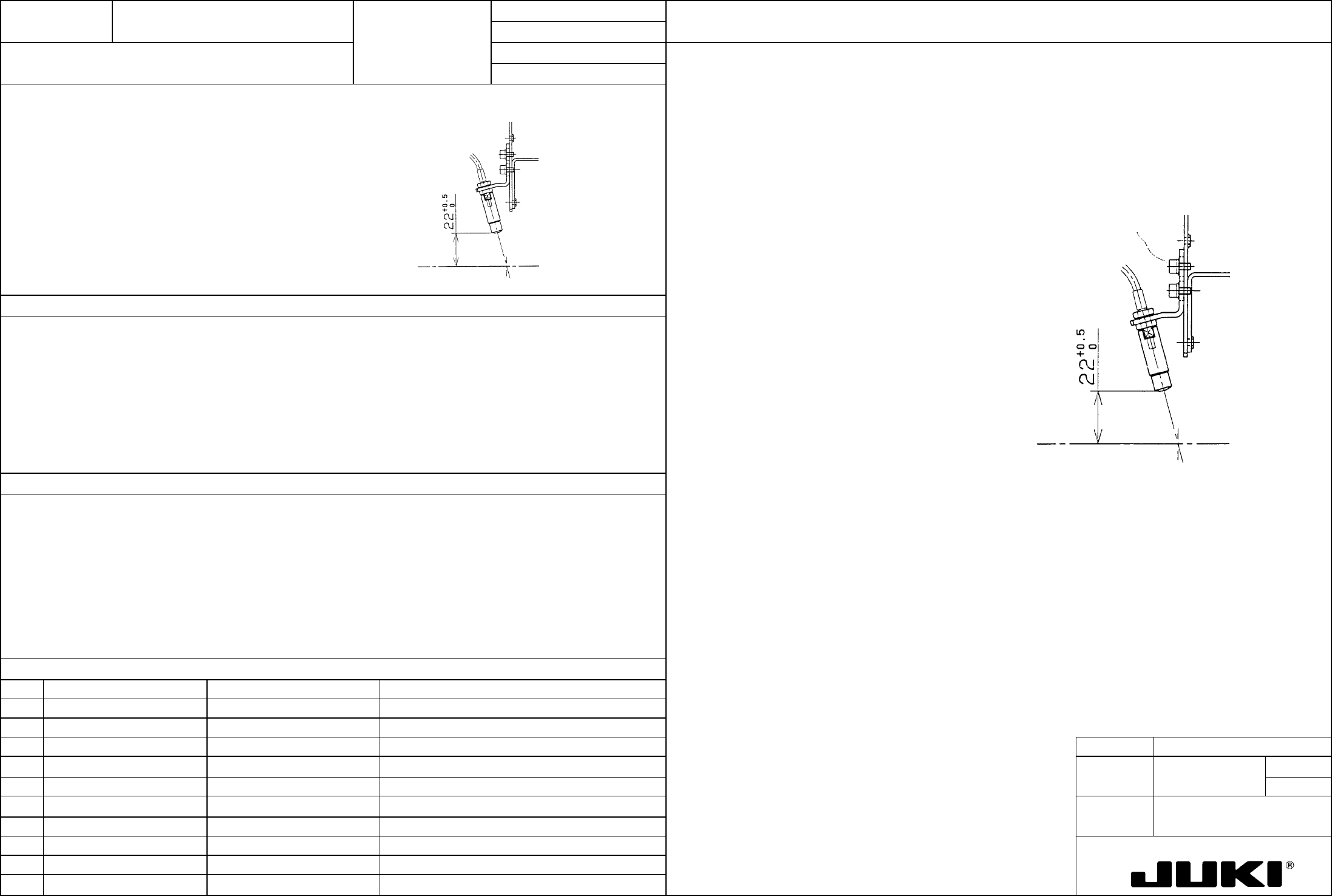
Move the bad mark sensor to a point above the calibration block. Loosen the SEMS cap bolts (a) at two places
and move the BM lens holder so that the distance between the bottom surface of the bad mark sensor and top
surface of calibration block becomes 22 +0.5/0 mm. When the specified distance is reached, secure the bad
mark sensor with SEMS cap bolts (a).
Distance between the bottom surface of bad mark sensor and top surface of calibration block: 22 +0.5/0 mm
Calibration bloc
k
top surface
SEMS cap (a)
– Bad mark detection error
– Contact with a 20-mm-high component
FUNCTION NAME HMS Height Function/Performance CHECK/ADJUSTMENT METHODS (REMEDIAL ACTION PROCEDURE)
ASSURED QUALITY Reliability
QUALITY CHARACTERISTICS (SPECIFICATION VALUES) CATEGORY Safety
Product Image
ROLE IN FUNCTION (MEANING OF SPECIFICATION VALUES)
POSSIBLE MALFUNCTIONS (CAUSED BY INCORRECT SPECIFICATION VALUES)
COMPONENTS
NO. Part No. Part Name Associated Quality Characteristics
1
2
3 MODEL KE-750/760
4
UNIT HMS
REF. NO.
5
NAME
26
6
FUNCTION HMS Height
7
NAME
8
9
10
QA Table
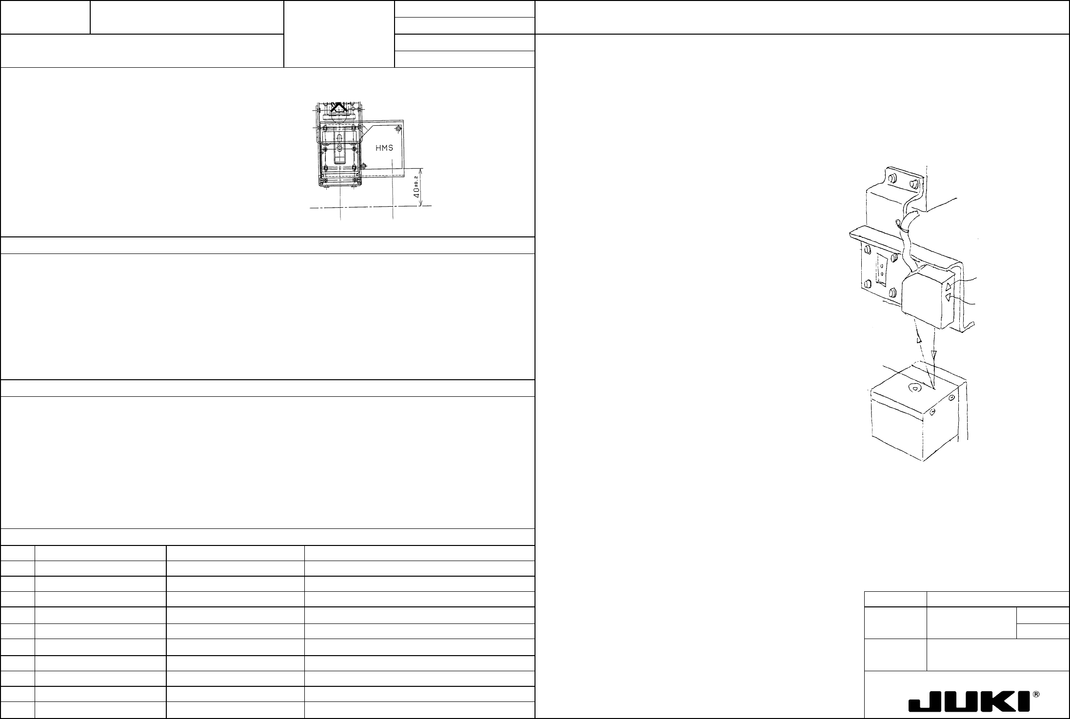
Move the HMS sensor to a point above the calibration block. Loosen the SEMS cap bolts (a) at four places and
adjust so that the distance between the bottom surface of the height sensor and top surface of calibration block
becomes 40 ±0.2 mm. When the specified distance is reached, secure the height sensor with SEMS cap bolts
Distance between the bottom surface of the height sensor and top surface of calibration block: 4 ±0.2 mm
Calibration bloc
k
top surface
(a). At this time, make sure that both the FAR lamp and NEAR lamp are lit up.
Calibration bloc
k
NEAR lamp
FAR lamp
Height senso
r
SEMS cap (a)
– Erroneous height measurement
FUNCTION NAME Stopper Assembly PWB Detection Function/Performance CHECK/ADJUSTMENT METHODS (REMEDIAL ACTION PROCEDURE)
ASSURED QUALITY Reliability
QUALITY CHARACTERISTICS (SPECIFICATION VALUES) CATEGORY Safety
Product Image
ROLE IN FUNCTION (MEANING OF SPECIFICATION VALUES)
POSSIBLE MALFUNCTIONS (CAUSED BY INCORRECT SPECIFICATION VALUES)
COMPONENTS
NO. Part No. Part Name Associated Quality Characteristics
1 E94657250A0 Stop sensor cable assembly
2 E94667250A0 C. OUT sensor cable assembly
3 SL4031291SC 9465/9466 SEMS cap MODEL KE-750/760
4 UNIT Transport REF. NO.
5
NAME
1
6 FUNCTION Stopper Assembly PWB
7
NAME Detection
8
9
10
QA Table
E2130725OAO
Stopper L assembly
Press against right
side of slit. (8)
116 (Be careful abou
t
contact with stopper tip.)
E2125725OAO
Stopper R assembly
116 (Be careful abou
t
contact with stopper tip.)
Press against left
side of slit. (8)
C. OUT senso
r
Stop senso
r
A
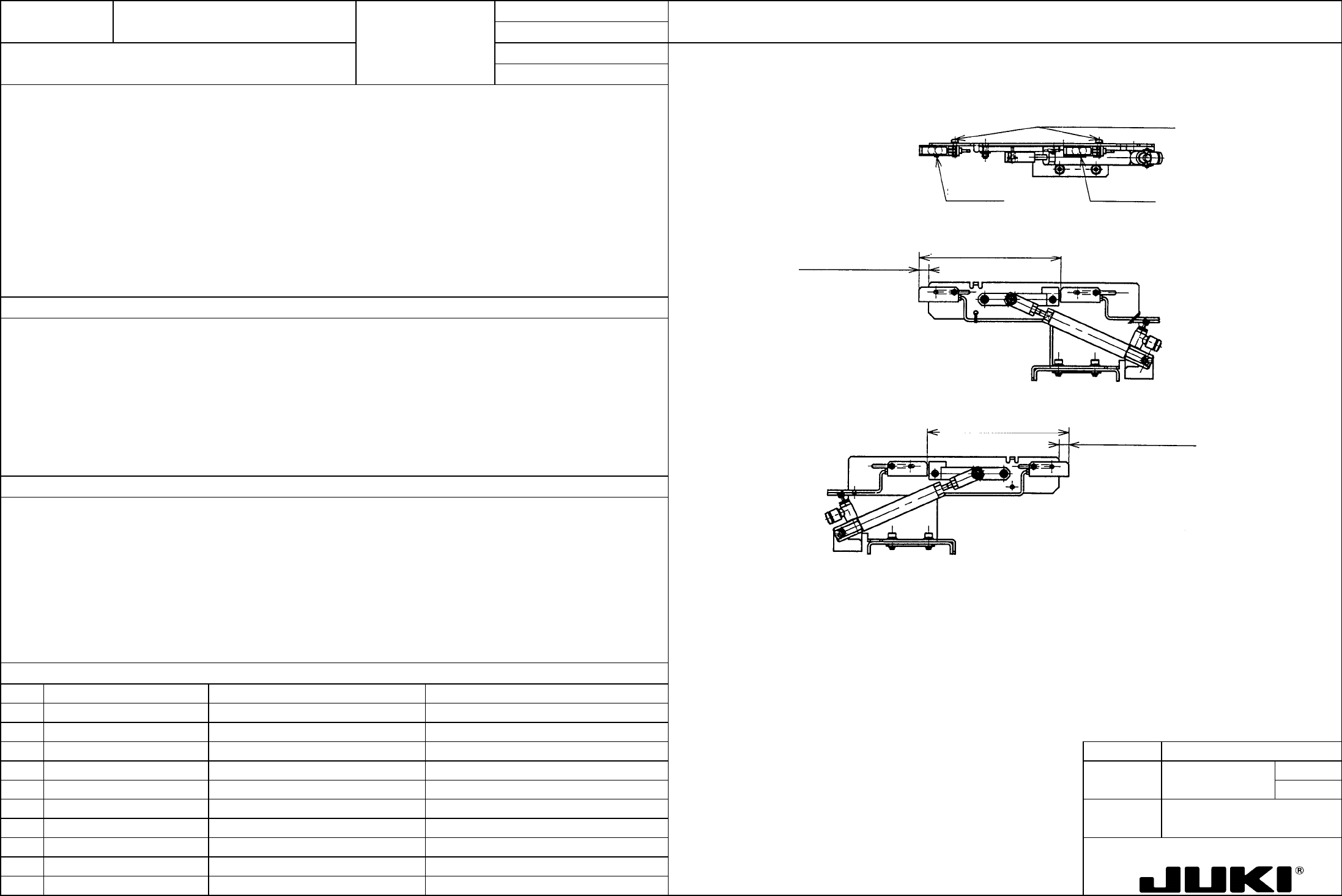
djusting screws (SL4031291SC)1. Stop sensor position: (8 mm) (See Fig. on the right.)
2. C. OUT sensor position 116 mm (See Fig. on the right.)
1. CENT motor stop signal trigger generation timing
2. IN motor start trigger generating timing (when transporting PWBs from the IN buffer to center buffer)
1. Severe collision of the PWB with the stopper due to insufficient deceleration of PWB. (Solution: Make the value smaller
than 8, which, however, results in further beyond the stopper frame.)
PWB failing to reach the stopper due to excessive deceleration. (Solution: Make the value larger than 8.)
2. Increased PWB transport tact time due to delayed starting of IN motor.