KE-750_QA表.pdf - 第70页
760 MODEL KE-750/ UNIT Electrical REF. NO. NAME EL-4 FUNCTION Z-Axis/ θ -Axis Servo Driver NAME Parameters 7/8 QA Table Parameter Descriptions (Speed Control Type) – Parameter Listing Table 8-7-1 Scree n Mode 0 (Key inpu…
MODEL KE-750/760
UNIT Electrical REF. NO.
NAME
EL-4
FUNCTION Z-Axis/θ-Axis Servo Driver
NAME Parameters 6/8
QA Table
(Setting Exercise)
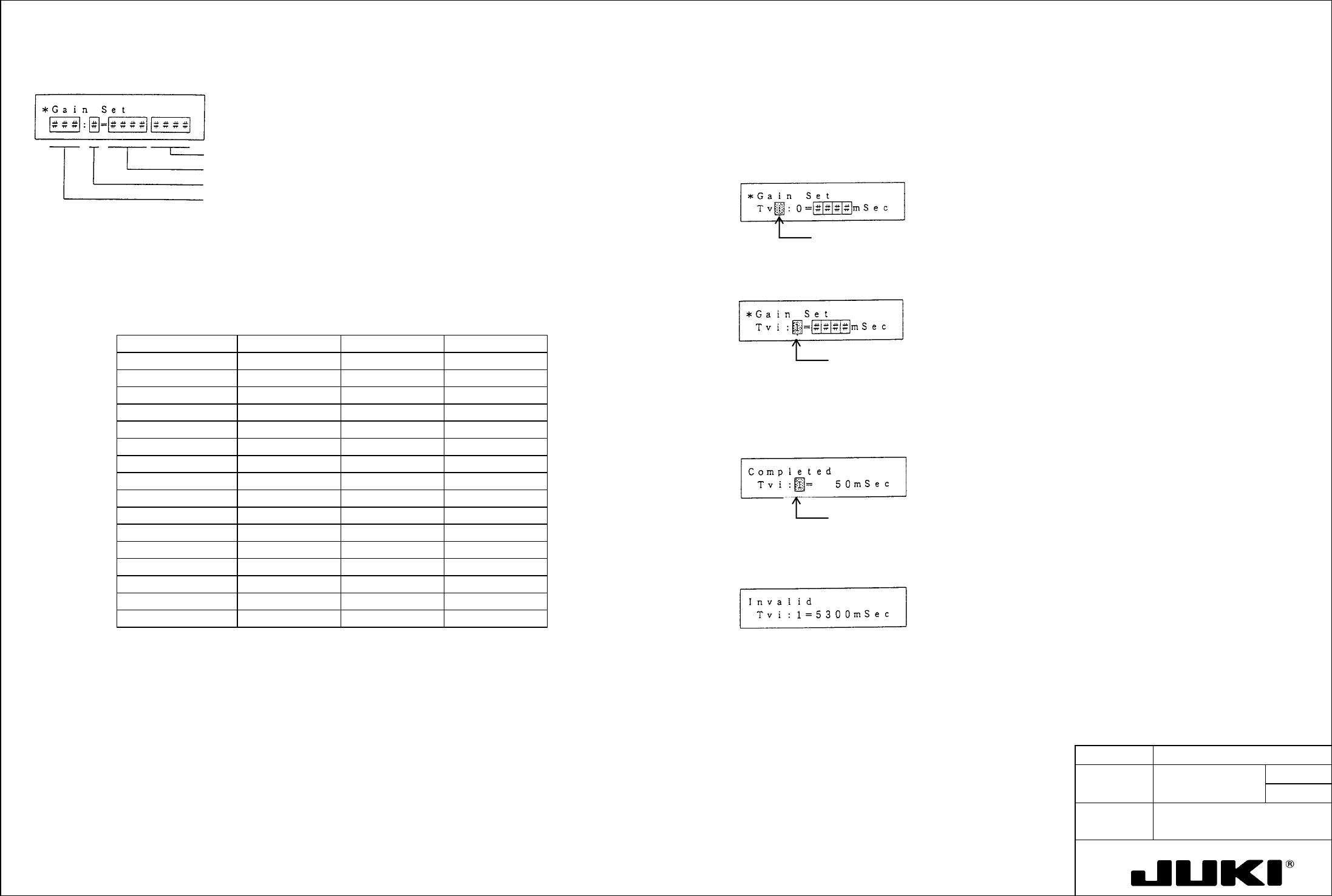
Gain setting mode (screen mode 5)
Let's set, for example, Tvi:1 to 50 msec.
Unit
Setting value data
Gain setting switch (RSW) value 0 to F
Parameter type Kp, Kvp, Tvi
Step 1. Set bit 7 of SSW2 to "1."
Return the mode select screen and select screen mode 5.
Step 2. Using > or <, move the cursor to the desired parameter type and, using
↓ or ↑, select Tvi.
Cursor blinks.
When in this mode, you can change the parameter (Kp, Kvp, Tvi) corresponding to the value set with the gain setting switch
(RSW) when the selector switch (SW) on the amplifier front panel is placed in the upper position to any desired value. The
following table shows the relation between the gain setting switch and the set parameter.
Step 3. Using > or <, move the cursor to the gain setting switch value and, using ↓ or ↑, select 1.
Table 7-9 Gain Setting Switch and Gain Setting Values
(Figures in parentheses are factory settings.)
Cursor blinks.
Gain setting switch Kp Kvp Tvi
0 Kp: 0 ( 10) Kvp: 0 ( 100) Tvi: 0 ( 20)
1 Kp:1 ( 10) Kvp: 1 ( 20) Tvi: 1 ( 20)
Step 4. Using > or <, move the cursor to the digit of the setting data in which you want to enter a value.
2 Kp: 2 ( 20) Kvp: 2 ( 35) Tvi: 2 ( 50)
Step 5. Using the numeric keys 0 to 9, enter "50" consecutively.
3 Kp: 3 ( 20) Kvp: 3 ( 35) Tvi: 3 ( 50)
Step 6. Press WR to store the data in nonvolatile memory.
4 Kp: 4 ( 30) Kvp: 4 ( 50) Tvi: 4 ( 50)
When the data has been set, the following message appears:
5 Kp: 5 ( 30) Kvp: 5 ( 50) Tvi: 5 ( 20)
Cursor blinks.
6 Kp: 6 ( 30) Kvp: 6 ( 70) Tvi: 6 ( 50)
7 Kp: 7 ( 30) Kvp: 7 ( 70) Tvi: 7 ( 20)
8 Kp: 8 ( 45) Kvp: 8 ( 100) Tvi: 8 ( 50)
9 Kp: 9 ( 45) Kvp: 9 ( 100) Tvi: 9 ( 20)
A Kp: A ( 45) Kvp: A ( 140) Tvi: A ( 50)
If a value has been entered that falls outside the setting range, the following message appears and the remote
operator does not bother storing the data in memory.
B Kp: B ( 45) Kvp: B ( 140) Tvi: B ( 20)
C Kp: C ( 60) Kvp: C ( 200) Tvi: C ( 50)
D Kp: D ( 45) Kvp: 9 ( 200) Tvi: D ( 20)
E Kp: E ( 60) Kvp: E ( 280) Tvi: E ( 50)
F Kp: F ( 60) Kvp: F ( 280) Tvi: F ( 20)
5300 msec. has
been entered:
Example:
Step 7. Press MODE to go back to the initial screen.
In the gain setting mode, make the following settings: Kp:1 = 30 rad/s., Kvp:1 = 70, and Tvi:1 = 30 msec. Then, place the
selector switch (SW) on the amplifier front panel in the upper position and set the gain setting switch (RSW) to "1." In this
condition:
To set another data, repeat steps from step 2.
The 30 rad/s value is set for Kp (position loop gain), 70 for Kvp (proportional gain), and 30 ms for Tvi (integral time
constant).
Note: BEFORE SETTING THE OPERATOR INTO THE GAIN SETTING MODE, be sure set bit 7 of SSW2 (mode 0 - 11) to
"1."
760 MODEL KE-750/
UNIT Electrical REF. NO.
NAME
EL-4
FUNCTION Z-Axis/θ-Axis Servo Driver
NAME Parameters 7/8
QA Table
Parameter Descriptions (Speed Control Type)
– Parameter Listing
Table 8-7-1 Screen Mode 0 (Key input setting) Table 8-7-2 Screen Mode 0 (Key input setting)
Page
no.
Abbreviation Name and description Standard
value
Unit Setting
range
Remark
Page
no.
Abbreviation Name and description Standard
value
Unit Setting
range
Remark
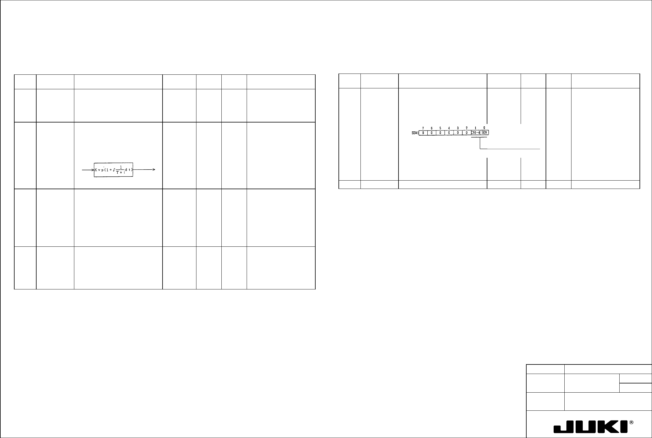
2 Kvp Speed loop proportional gain:
Proportional gain of the speed
controller (proportional integral
control).
70 — 10 to
3000
Data cannot be changed
from the operator when
the selector switch (SW)
on the amplifier front panel
is in the upper position.
10 SSW1 Selector switch 1:
- The desired function can be set
the digital switch.
00000000 bit 0.1 Select either external
signal enable or internal
force-ON.
3 Tvi Speed loop integral time constant:
Integrated time constant of the
speed controller (proportional
integral control).
20 mS 2 to
1000
Data cannot be changed
from the operator when
the selector switch (SW)
on the amplifier front panel
is in the upper position.
7 ENCR Output pulse dividing ratio:
The dividing ratio of encoder signal
(phase A, phase B) can be set.
Dividing ratio =
β/α
Where,
α .. 1 to 64, 8192
β... 1 (when α = 1 to 64)
2 (when
α= 3 to 64)
1 to 8191 (when
α= 8192)
1/1 — 1 to
1/8192
8
8 LTG Low speed:
- Set the speed of low speed
output.
- Low speed output LTG turns ON
when the speed slows down
below the set level.
50 min
-1
10 to
9999
Speed
deviation
Current
command
11
17/
18/ Enable external 19/ Internal force-ON
20/
21/ Selector switch 2:
- The desired function can be set the digital switch.
22/ Speed command polarity
0 | Turns forward with a "+" input.
1 | Turns forward with a "-" input.
Alarm output logic
0 | OFF when an alarm occurs.
1 | ON when an alarm occurs.
CN1-4 pin select
0 | PCON (P control)
1 | ZCMD (zero clamp)
Cch (CN1-35, 36) logic
0 | Tr ON with Cch output
1 | Tr OFF with Cch output
Test mode execution
0 | Disabled
1 | Enabled
System parameter overwrite enable
0 | Disabled
1 | Enabled
23/ Set bits 6 and 7 back to "0" after execution. They can also be reset to "0" by turning power OFF.
The bit 5 setting becomes valid only when power is once turned OFF.
24/ Z-Axis/$-Axis Servo Driver Parameters 7/8
MODEL KE-750/760
UNIT Electrical REF. NO.
NAME
EL-4
FUNCTION Z-Axis/θ-Axis Servo Driver
NAME Parameters 8/8
QA Table
Table 8-7-3 Screen Mode 0 (Key input setting) Table 8-8 Screen Mode 1 (Menu input setting)
Page
no.
Abbreviation Name and description Standard
value
Unit Setting
range
Remark Page
no.
Abbreviation Name and description Factory
setting
No. of options
available
Remark
12 Kvp Speed command LPF
- Set the cutoff frequency of the
primary low-pass filter for the
speed command input.
500
Hz 1 to 500
0 TYPE Control mode
- Position control, speed control
Velocit
y
2 Data can be
changed only after
bit 7 of SSW2 of
mode 0 - 11 is set
to "1."
13 ILPF Current command LPF
- Set the cutoff frequency of the
primary low-pass filter for the
current command within the speed
loop.
500 Hz 1 to 500
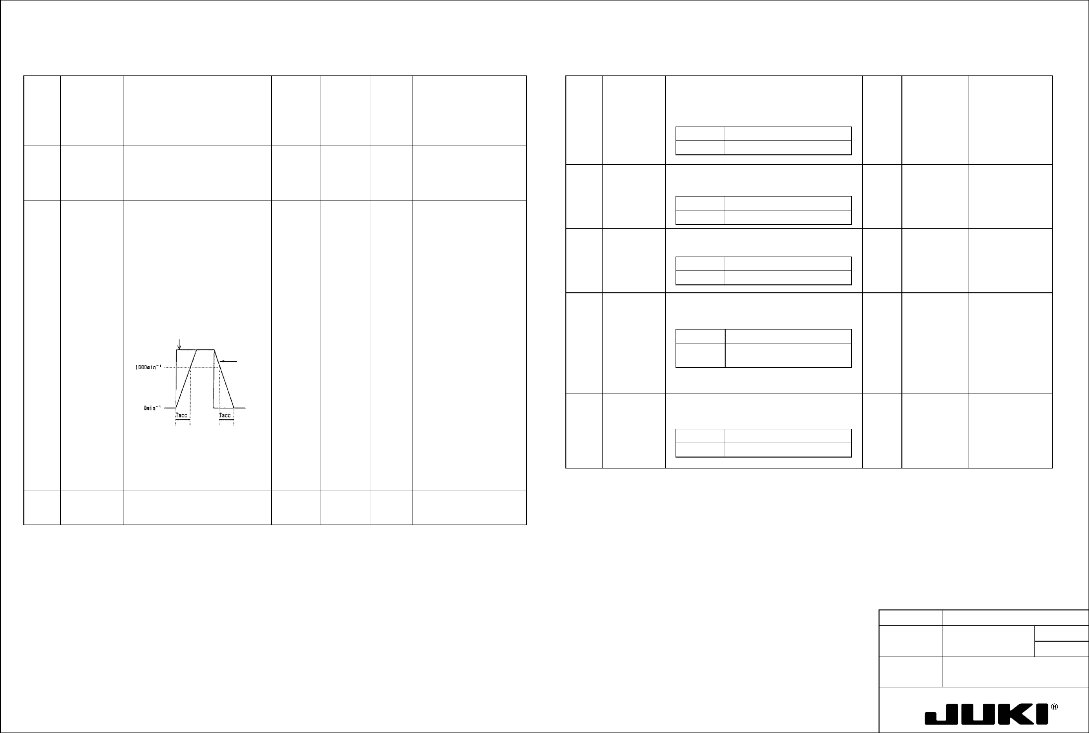
14 Tacc Speed command
acceleration/deceleration time
- Set the acceleration/deceleration
time over a change of 1000min
-1
.
- The speed command in the servo
amplifier is limited to keep
acceleration within the level
determined by this
acceleration/deceleration time
even with sudden changes in the
speed command voltage.
Note:
Set this parameter to "0" if a
position loop is formed outside the
servo amplifier, as an oscillation
could result.
0 x10ms 0 to 250 Data can be set in 10-ms
increments in the range 0
to 2500 ms.
16 Scal Speed scale
Vary the speed command scale of
analog inputs.
2000 mV/
1000min
-1
900 to
6666
Display Description
Velocity Speed control type
1 ENKD Encoder type
- Type of the encoder used
INC. E 1 This parameter
cannot be
changed.
Display Description
2000P/R Wire-saving incremental
2 ENPL No. of encoder pulses
- No. of pulses output by the encoder used
2000P/
R
1 This parameter
cannot be
changed.
Display Description
2000P/R 2000 pulses per revolution
3 MOT. Motor type
- Motor used (under a particular series)
Example:
$$$$: Depends the factory-set specifications.
$$$$ P30, P50
Under series
(by amplifier
capacity)
Data can be
changed only after
bit 7 of SSW2 of
mode 0 - 11 is set
to "1."
Display Description
2000P/R 50-W motor under P30 series
is selected.
Speed command
voltage
Internal speed
command
4 CABLE Applicable cable length
- Length of cable between motor and amplifier:
0 to 5 m, 5 to 10 m, 10 to 15 m, 15 to 20 m
0 -- 5m 4 Data can be
changed only after
bit 7 of SSW2 of
mode 0 - 11 is set
to "1."
Display Description
0 - - 5m Wiring length: Less than 5 m