KE-750_QA表.pdf - 第37页
FUNCTION NAME Supporting the PWB from Under side Function/Performance CHECK/ADJUST MENT METHODS (REMEDIAL ACT ION PROCEDURE) ASSURED QUALITY Reliability QUALITY CHARACTERISTI CS (SPECIFICATION VALUES) CATEGORY Safety Pro…
FUNCTION NAME Stopping the PWB Being Transported Function/Performance CHECK/ADJUSTMENT METHODS (REMEDIAL ACTION PROCEDURE)
ASSURED QUALITY Reliability
QUALITY CHARACTERISTICS (SPECIFICATION VALUES) CATEGORY Safety
Product Image
ROLE IN FUNCTION (MEANING OF SPECIFICATION VALUES)
POSSIBLE MALFUNCTIONS (CAUSED BY INCORRECT SPECIFICATION VALUES)
COMPONENTS
NO. Part No. Part Name Associated Quality Characteristics
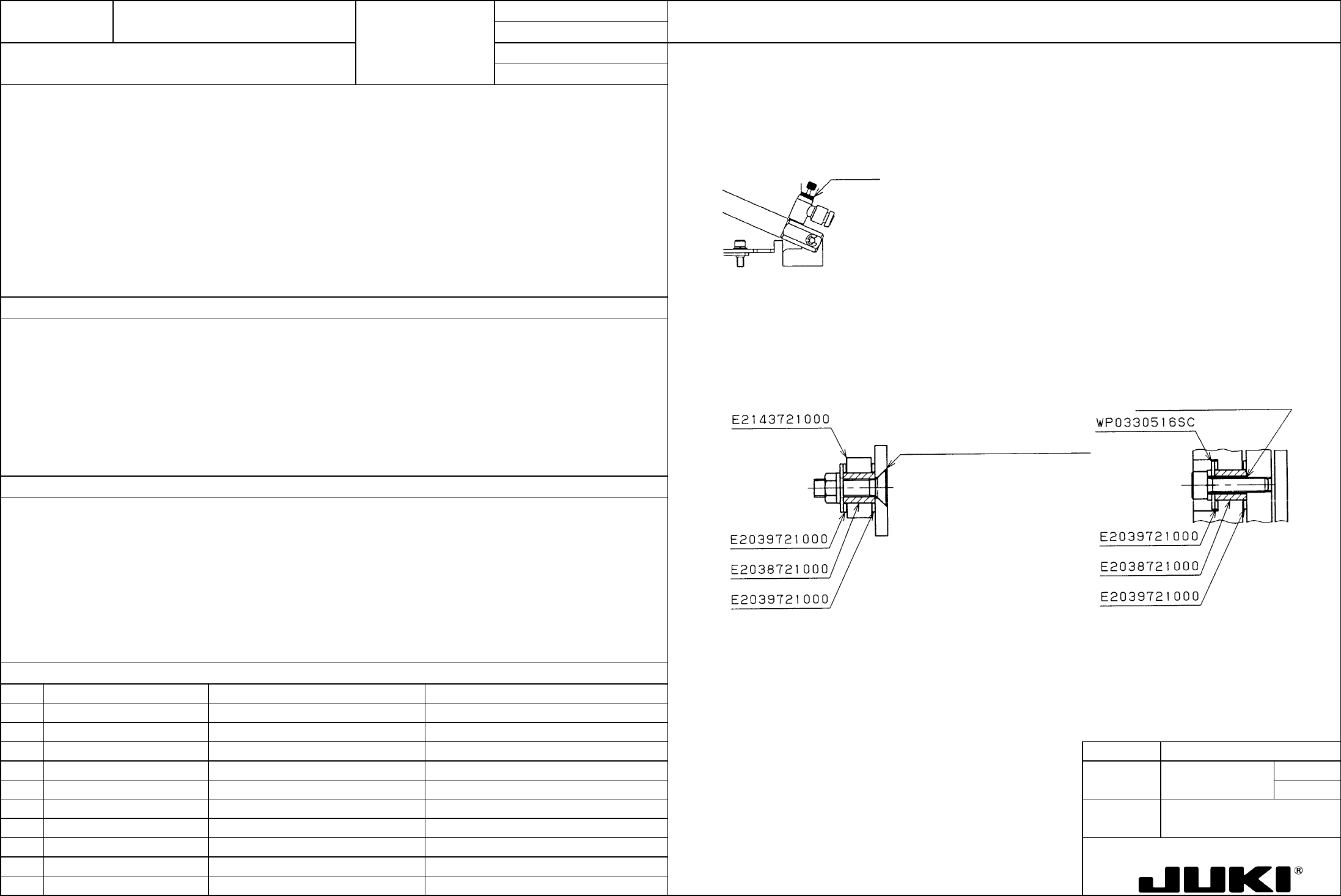
1 E2143721000 Stopper plate
2 E2039721000 Thrust washer
3 E2038721000 Stopper collar MODEL KE-750/760
4 UNIT Transport REF. NO.
5
NAME
7
6 FUNCTION Stopping the PWB Being
7
NAME Transported
8
9
10
QA Table
1. Speed controller opening angle: Two turns from the fully closed position.
1. Speed controller opening angle
2. The stopper plate must move smoothly.
Turn it two turns from the fully closed position and secure it in position with the lock nut.
Lock nut
2. Turn ON and OFF air to observe how the pressure plate moves. If it looks binding, check parts installed at the pivot of
the pressure plate and stopper clevis. A washer may be wedged in, a part may be missing, or the adhesive may be
squeezed out.
1. PWB clamping speed.
2. To maintain a given PWB clamping speed. To prevent interference with other parts.
Check to see i
f
adhesive is squeezed out.
Check to see if adhesive is
squeezed out on the opposite side.(stopper plate)
1. High speed: Ceramic and thin PWB cracked.
Low speed: Unable to stop the PWB at a good position.
2. The stopper frame does not move and the PWB cannot be stopped.
The stopper frame is slow to move and the PWB cannot be stopped at a good position.
FUNCTION NAME Supporting the PWB from Underside Function/Performance CHECK/ADJUSTMENT METHODS (REMEDIAL ACTION PROCEDURE)
ASSURED QUALITY Reliability
QUALITY CHARACTERISTICS (SPECIFICATION VALUES) CATEGORY Safety
Product Image
ROLE IN FUNCTION (MEANING OF SPECIFICATION VALUES)
POSSIBLE MALFUNCTIONS (CAUSED BY INCORRECT SPECIFICATION VALUES)
COMPONENTS
NO. Part No. Part Name Associated Quality Characteristics
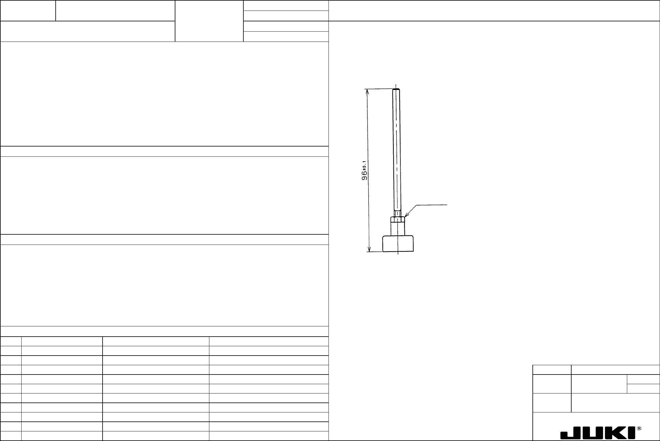
1 E20217150A0 Backup pin assembly
2
3 MODEL KE-750/760
4 UNIT Transport REF. NO.
5
NAME
8
6 FUNCTION Supporting the PWB from
7
NAME Underside
8
9
10
QA Table
1. Loosen the adjusting nut, determine the pin height, and then secure the adjusting nut.
1. Pin height: 96 ±0.1 mm
A
djusting nut
1. Adjustment of height from BT table top surface to PWB bottom surface
1. Too high: The BU pin pushes the PWB up.
Too low: The BU pin does not reach the PWB.
FUNCTION NAME Feeding PWBs Smoothly - 2 Function/Performance CHECK/ADJUSTMENT METHODS (REMEDIAL ACTION PROCEDURE)
ASSURED QUALITY Reliability
QUALITY CHARACTERISTICS (SPECIFICATION VALUES) CATEGORY Safety
Product Image
ROLE IN FUNCTION (MEANING OF SPECIFICATION VALUES)
POSSIBLE MALFUNCTIONS (CAUSED BY INCORRECT SPECIFICATION VALUES)
COMPONENTS
NO. Part No. Part Name Associated Quality Characteristics
1 E2017725000 Transport belt S
2 E2016725000 Transport belt C
3 E2046725000 PWB inner MODEL KE-750/760
4 E2051721000 Drive belt UNIT Transport REF. NO.
5 E2014725000 Drive belt C
NAME
9
6 E2011725000 Drive shaft S FUNCTION Feeding PWBs Smoothly - 2
7 E2004725000 Drive shaft C
NAME
8
9
10
QA Table
1. Mark the transport belt at 200-mm intervals and pull the adjustment pulley so that the distance between the two adjacent
markings measures 202 mm.
1. Transport belt tension: Keep the belt taut with its length stretched by 1% from its free length.
2. Transport pulley movement: The pulley should move smoothly with the belt.
2. The transport pulley should turn smoothly when the belt is driven.
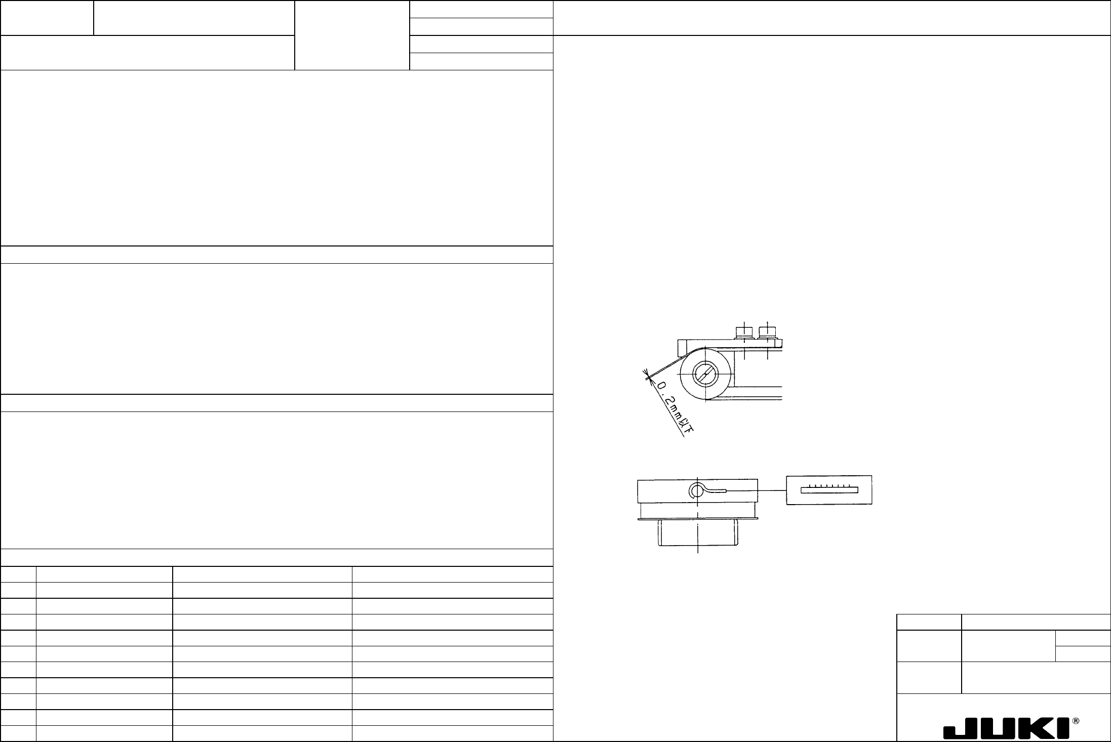
3. Clearance between PWB inner and transport belt: Within 0.2 mm
If it does not turn smoothly, check for sufficient clearance from the PWB inner and a pulley set screw (axis center) left
loose.
4. Transport belt joint thickness: 1 +0.15/-0.1 mm
5. Motor belt C tension: 1.8 to 2.2 kgf
Check grease on drive pulley R x thrust washer x rail plate R.
6. Motor belt tension: 2.7 to 3.3 kgf
Check to see if a thrust washer is wedged in mechanism.
7. Drive shaft torque: 0.2 N.m or less
The optimum gap in drive pulley is 0.3 to 0.5 mm.
3. Apply a 0.2-mm-dia. bar to the space between the PWB inner and transport belt and assemble parts with care not to allow
an excessive gap. Too narrow a gap results in the PWB inner and the belt getting too close together (especially at the
joint).
5. Take measurements using an acoustic wave type belt tensiometer (manufactured by Unitta).
(weight: 0.25, width: 6.0, span: 88)
6. Take measurements using an acoustic wave type belt tensiometer (manufactured by Unitta).
(weight: 0.25, width: 6.0, span: 78)
7. Insert a pin into the set screw tapped hole in drive pulley F and pull the pin end with a spring balance to measure the
starting torque. If the torque is heavy, check for a pulley thrust washer wedged in mechanism and a warped drive shaft.
1 to 4. To drive the transport belt with sufficient clearance or no slip.
5 to 7. To set the optimum torque of the drive shaft. To prevent the timing belt from skipping cogs.
1. Transport belt too slack -> Belt slipping
Transport belt too tight -> Drive shaft torque increased, belt snapping off.
2. Binding transport pulley -> Transport belt stopped, transport motor out of correct timing, generating heat.
3. No gap -> Belt and PWB inner get too close together, belt stopped, transport motor out of correct timing, generating heat.
4. Thick joint -> PWB inner and radius get too close together, belt stopped, transport motor out of correct timing, generating
heat.
5, 6. Too tight -> Large drive shaft torque
Too slack -> Belt cogs being skipped
7. Heavy torque -> Transport motor out of correct timing, generating heat. Transport belt stopped.