818306-01_Recommended_mating_shafts_manual_en_web.pdf - 第9页
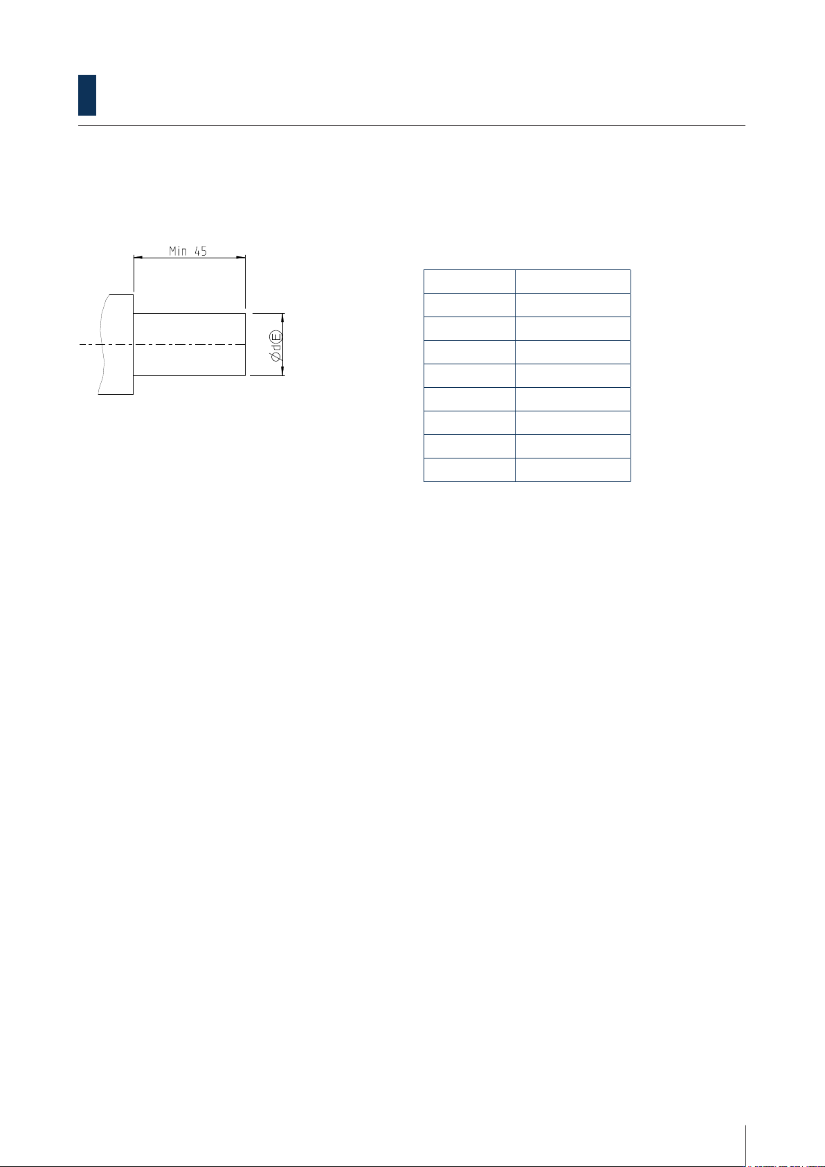
Recommended mating shafts HOLLOW SHAFT ENCODERS ww w .leinelinde.com 9 2.3 700 series 2.3.1 Through-going hollow shaft with clamping ring Dimensions Ød T olerance 12 mm g6 14 mm g6 16 mm g6 20 mm g6 25 mm g6 5/8 inch g6 …
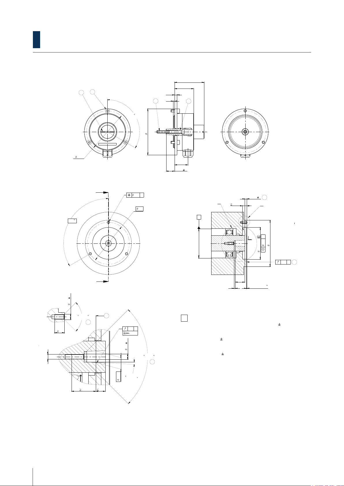
Recommended mating shafts
HOLLOW SHAFT ENCODERS www.leinelinde.com
8
B
B
1
2
3
4
5 6 7 8
9
10
11
12
A
B
C
D
E
F
G
H
1 2
3
4
5
6
7
8
A
B
C
D
E
F
9 10 11
12
G
H
-
-
-
-0.3 +0.3
Box 8 S-645 21 Strangnas, Sweden
D
47
30.5
4
2
21.25
13.5 3
3.5
3
15
3
19.5
4
1362047-01
ll_a2
Change No. C122029-01 Text:
Part number
Phase: Serial production
Unless otherwise specified Surface treatment:
Scale Format
1:1 A2 Blank part number
General tolerances ISO 2768 -1m
MZI interface
Tolerances as per ISO 8015
Surfaces as per ISO 1302
Mating Dimensions
The reproduction, distribution and utilization of this document as well as the communication of its contents to others without express authorization is prohibited.
Offenders will be held liable for the payment of damages. All rights reserved in the event of the grant of a patent, utility model or design. ( ISO 16016 )
Workpiece edges ISO 13715
Created Released
Material:
Version Revision Sheet Page
1362069 00 A 03
1
of
1
Asterlund Asterlund
21.09.2021 17.02.2022
Document number
A = Bearing of mating shaft
1 = Screw plug, width 2mm, tightening torque 2 0.5Nm
2 = Screw ISO 4762 - M4 x 40-A2,
with material bonding anti-rotation lock,
tightening torque 2 0.5Nm.
3 = Screw ISO 4762 - M4 x 10-A2,
with material bonding anti-rotation lock,
tightening torque 2 0.5Nm
4 = Functional diameter of taper
5 = Chamfer is mandatory at start of thread for
materially bonding anti-rotation lock.
6 = Flange surface; ensure full-surface contact.
7 = Maximum permissible deviation between shaft and
flange surfaces.
Compensation of mounting tolerances and thermal expansions.
Dynamic motion permitted over entire range.
8 = M5 back-off thread.
5
6
7
5
Required mating dimensions
1
3
8
2
B-B
A
B
2:1
A
2:1
B
+0,5
A
74
67
120 (3x)
50.8 H7
67
3x M4
8
3x 120
0.5 x 15
74
4.5
0.1
90 ... 120
2
M4
9.25
7.5
4.5
0.1
90 ... 120
2 51'45"
0
-0 1'
0.1 A
0.2 A
0.1 A
0.1 A
1:10
B
B
1
2
3
4
5 6 7 8
9
10
11
12
A
B
C
D
E
F
G
H
1 2
3
4
5
6
7
8
A
B
C
D
E
F
9 10 11
12
G
H
-
-
-
-0.3 +0.3
Box 8 S-645 21 Strangnas, Sweden
D
47
30.5
4
2
21.25
13.5 3
3.5
3
15
3
19.5
4
1362047-01
ll_a2
Change No. C122029-01 Text:
Part number
Phase: Serial production
Unless otherwise specified Surface treatment:
Scale Format
1:1 A2 Blank part number
General tolerances ISO 2768 -1m
MZI interface
Tolerances as per ISO 8015
Surfaces as per ISO 1302
Mating Dimensions
The reproduction, distribution and utilization of this document as well as the communication of its contents to others without express authorization is prohibited.
Offenders will be held liable for the payment of damages. All rights reserved in the event of the grant of a patent, utility model or design. ( ISO 16016 )
Workpiece edges ISO 13715
Created Released
Material:
Version Revision Sheet Page
1362069 00 A 03
1
of
1
Asterlund Asterlund
21.09.2021 17.02.2022
Document number
A = Bearing of mating shaft
1 = Screw plug, width 2mm, tightening torque 2 0.5Nm
2 = Screw ISO 4762 - M4 x 40-A2,
with material bonding anti-rotation lock,
tightening torque 2 0.5Nm.
3 = Screw ISO 4762 - M4 x 10-A2,
with material bonding anti-rotation lock,
tightening torque 2 0.5Nm
4 = Functional diameter of taper
5 = Chamfer is mandatory at start of thread for
materially bonding anti-rotation lock.
6 = Flange surface; ensure full-surface contact.
7 = Maximum permissible deviation between shaft and
flange surfaces.
Compensation of mounting tolerances and thermal expansions.
Dynamic motion permitted over entire range.
8 = M5 back-off thread.
5
6
7
5
Required mating dimensions
1
3
8
2
B-B
A
B
2:1
A
2:1
B
+0,5
A
74
67
120 (3x)
50.8 H7
67
3x M4
8
3x 120
0.5 x 15
74
4.5
0.1
90 ... 120
2
M4
9.25
7.5
4.5
0.1
90 ... 120
2 51'45"
0
-0 1'
0.1 A
0.2 A
0.1 A
0.1 A
1:10
B
B
1
2
3
4
5 6 7 8
9
10
11
12
A
B
C
D
E
F
G
H
1 2
3
4
5
6
7
8
A
B
C
D
E
F
9 10 11
12
G
H
-
-
-
-0.3 +0.3
Box 8 S-645 21 Strangnas, Sweden
D
47
30.5
4
2
21.25
13.5 3
3.5
3
15
3
19.5
4
1362047-01
ll_a2
Change No. C122029-01 Text:
Part number
Phase: Serial production
Unless otherwise specified Surface treatment:
Scale Format
1:1 A2 Blank part number
General tolerances ISO 2768 -1m
MZI interface
Tolerances as per ISO 8015
Surfaces as per ISO 1302
Mating Dimensions
The reproduction, distribution and utilization of this document as well as the communication of its contents to others without express authorization is prohibited.
Offenders will be held liable for the payment of damages. All rights reserved in the event of the grant of a patent, utility model or design. ( ISO 16016 )
Workpiece edges ISO 13715
Created Released
Material:
Version Revision Sheet Page
1362069 00 A 03
1
of
1
Asterlund Asterlund
21.09.2021 17.02.2022
Document number
A = Bearing of mating shaft
1 = Screw plug, width 2mm, tightening torque 2 0.5Nm
2 = Screw ISO 4762 - M4 x 40-A2,
with material bonding anti-rotation lock,
tightening torque 2 0.5Nm.
3 = Screw ISO 4762 - M4 x 10-A2,
with material bonding anti-rotation lock,
tightening torque 2 0.5Nm
4 = Functional diameter of taper
5 = Chamfer is mandatory at start of thread for
materially bonding anti-rotation lock.
6 = Flange surface; ensure full-surface contact.
7 = Maximum permissible deviation between shaft and
flange surfaces.
Compensation of mounting tolerances and thermal expansions.
Dynamic motion permitted over entire range.
8 = M5 back-off thread.
5
6
7
5
Required mating dimensions
1
3
8
2
B-B
A
B
2:1
A
2:1
B
+0,5
A
74
67
120 (3x)
50.8 H7
67
3x M4
8
3x 120
0.5 x 15
74
4.5
0.1
90 ... 120
2
M4
9.25
7.5
4.5
0.1
90 ... 120
2 51'45"
0
-0 1'
0.1 A
0.2 A
0.1 A
0.1 A
1:10
B
B
1
2
3
4
5 6 7 8
9
10
11
12
A
B
C
D
E
F
G
H
1 2
3
4
5
6
7
8
A
B
C
D
E
F
9 10 11
12
G
H
-
-
-
-0.3 +0.3
Box 8 S-645 21 Strangnas, Sweden
D
47
30.5
4
2
21.25
13.5 3
3.5
3
15
3
19.5
4
1362047-01
ll_a2
Change No. C122029-01 Text:
Part number
Phase: Serial production
Unless otherwise specified Surface treatment:
Scale Format
1:1 A2 Blank part number
General tolerances ISO 2768 -1m
MZI interface
Tolerances as per ISO 8015
Surfaces as per ISO 1302
Mating Dimensions
The reproduction, distribution and utilization of this document as well as the communication of its contents to others without express authorization is prohibited.
Offenders will be held liable for the payment of damages. All rights reserved in the event of the grant of a patent, utility model or design. ( ISO 16016 )
Workpiece edges ISO 13715
Created Released
Material:
Version Revision Sheet Page
1362069 00 A 03
1
of
1
Asterlund Asterlund
21.09.2021 17.02.2022
Document number
A = Bearing of mating shaft
1 = Screw plug, width 2mm, tightening torque 2 0.5Nm
2 = Screw ISO 4762 - M4 x 40-A2,
with material bonding anti-rotation lock,
tightening torque 2 0.5Nm.
3 = Screw ISO 4762 - M4 x 10-A2,
with material bonding anti-rotation lock,
tightening torque 2 0.5Nm
4 = Functional diameter of taper
5 = Chamfer is mandatory at start of thread for
materially bonding anti-rotation lock.
6 = Flange surface; ensure full-surface contact.
7 = Maximum permissible deviation between shaft and
flange surfaces.
Compensation of mounting tolerances and thermal expansions.
Dynamic motion permitted over entire range.
8 = M5 back-off thread.
5
6
7
5
Required mating dimensions
1
3
8
2
B-B
A
B
2:1
A
2:1
B
+0,5
A
74
67
120 (3x)
50.8 H7
67
3x M4
8
3x 120
0.5 x 15
74
4.5
0.1
90 ... 120
2
M4
9.25
7.5
4.5
0.1
90 ... 120
2 51'45"
0
-0
1'
0.1 A
0.2 A
0.1 A
0.1 A
1:10
B
B
1
2
3
4
5 6 7 8
9
10
11
12
A
B
C
D
E
F
G
H
1 2
3
4
5
6
7
8
A
B
C
D
E
F
9 10 11
12
G
H
-
-
-
-0.3 +0.3
Box 8 S-645 21 Strangnas, Sweden
D
47
30.5
4
2
21.25
13.5 3
3.5
3
15
3
19.5
4
1362047-01
ll_a2
Change No. C122029-01 Text:
Part number
Phase: Serial production
Unless otherwise specified Surface treatment:
Scale Format
1:1 A2 Blank part number
General tolerances ISO 2768 -1m
MZI interface
Tolerances as per ISO 8015
Surfaces as per ISO 1302
Mating Dimensions
The reproduction, distribution and utilization of this document as well as the communication of its contents to others without express authorization is prohibited.
Offenders will be held liable for the payment of damages. All rights reserved in the event of the grant of a patent, utility model or design. ( ISO 16016 )
Workpiece edges ISO 13715
Created Released
Material:
Version Revision Sheet Page
1362069 00 A 03
1
of
1
Asterlund Asterlund
21.09.2021 17.02.2022
Document number
A = Bearing of mating shaft
1 = Screw plug, width 2mm, tightening torque 2
0.5Nm
2 = Screw ISO 4762 - M4 x 40-A2,
with material bonding anti-rotation lock,
tightening torque 2
0.5Nm.
3 = Screw ISO 4762 - M4 x 10-A2,
with material bonding anti-rotation lock,
tightening torque 2
0.5Nm
4 = Functional diameter of taper
5 = Chamfer is mandatory at start of thread for
materially bonding anti-rotation lock.
6 = Flange surface; ensure full-surface contact.
7 = Maximum permissible deviation between shaft and
flange surfaces.
Compensation of mounting tolerances and thermal expansions.
Dynamic motion permitted over entire range.
8 = M5 back-off thread.
5
6
7
5
Required mating dimensions
1
3
8
2
B-B
A
B
2:1
A
2:1
B
+0,5
A
74
67
120 (3x)
50.8 H7
67
3x M4
8
3x 120
0.5 x 15
74
4.5
0.1
90 ... 120
2
M4
9.25
7.5
4.5
0.1
90 ... 120
2 51'45"
0
-0 1'
0.1 A
0.2 A
0.1 A
0.1 A
1:10
2.2.4 Tapered shaft 1:10 (IBI 6x1)
B
B
1
2
3
4
5 6 7 8
9
10
11
12
A
B
C
D
E
F
G
H
1 2
3
4
5
6
7
8
A
B
C
D
E
F
9 10 11
12
G
H
-
-
-
-0.3 +0.3
Box 8 S-645 21 Strangnas, Sweden
D
47
30.5
4
2
21.25
13.5 3
3.5
3
15
3
19.5
4
1362047-01
ll_a2
Change No. C122029-01 Text:
Part number
Phase: Serial production
Unless otherwise specified Surface treatment:
Scale Format
1:1 A2 Blank part number
General tolerances ISO 2768 -1m
MZI interface
Tolerances as per ISO 8015
Surfaces as per ISO 1302
Mating Dimensions
The reproduction, distribution and utilization of this document as well as the communication of its contents to others without express authorization is prohibited.
Offenders will be held liable for the payment of damages. All rights reserved in the event of the grant of a patent, utility model or design. ( ISO 16016 )
Workpiece edges ISO 13715
Created Released
Material:
Version Revision Sheet Page
1362069 00 A 03
1
of
1
Asterlund Asterlund
21.09.2021 17.02.2022
Document number
A = Bearing of mating shaft
1 = Screw plug, width 2mm, tightening torque 2 0.5Nm
2 = Screw ISO 4762 - M4 x 40-A2,
with material bonding anti-rotation lock,
tightening torque 2 0.5Nm.
3 = Screw ISO 4762 - M4 x 10-A2,
with material bonding anti-rotation lock,
tightening torque 2 0.5Nm
4 = Functional diameter of taper
5 = Chamfer is mandatory at start of thread for
materially bonding anti-rotation lock.
6 = Flange surface; ensure full-surface contact.
7 = Maximum permissible deviation between shaft and
flange surfaces.
Compensation of mounting tolerances and thermal expansions.
Dynamic motion permitted over entire range.
8 = M5 back-off thread.
5
6
7
5
Required mating dimensions
1
3
8
2
B-B
A
B
2:1
A
2:1
B
+0,5
A
74
67
120 (3x)
50.8 H7
67
3x M4
8
3x 120
0.5 x 15
74
4.5
0.1
90 ... 120
2
M4
9.25
7.5
4.5
0.1
90 ... 120
2 51'45"
0
-0 1'
0.1 A
0.2 A
0.1 A
0.1 A
1:10
Recommended mating shafts
HOLLOW SHAFT ENCODERS www.leinelinde.com
9
2.3 700 series
2.3.1 Through-going hollow shaft with clamping ring
Dimensions
Ød Tolerance
12 mm g6
14 mm g6
16 mm g6
20 mm g6
25 mm g6
5/8 inch g6
3/4 inch g6
1 inch g6
Recommended mating shafts
HOLLOW SHAFT ENCODERS www.leinelinde.com
10
2.4 800 series
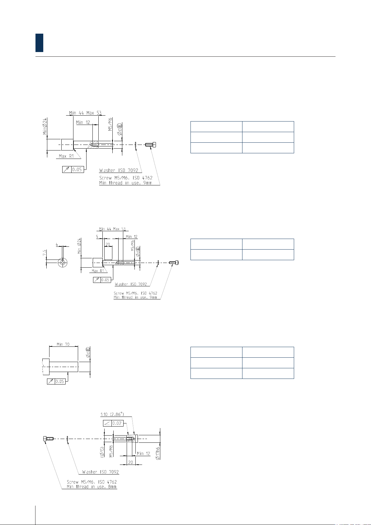
2.4.1 Blind hollow shaft with axial xing screw
2.4.2 Blind hollow shaft with axial xing screw and keyway
2.4.3 Through-going hollow shaft with clamping ring
2.4.4 Taper hollow shaft with axial xing screw
Dimensions [mm]
Ød Tolerance
12 js6
16 js6
Dimensions [mm]
Ød Tolerance
12 js6
Dimensions
Ød Tolerance
1 inch g6
25 mm g6
When a 53 mm mating shaft is used the recommend-
ed screw length is 16 mm. If the shaft is made shorter
the length of the screw must be prolonged accord-
ingly so that minimum 9 mm thread is in use.
When a 53 mm mating shaft is used the recommend-
ed screw length is 16 mm. If the shaft is made shorter
the length of the screw must be prolonged accord-
ingly so that minimum 9 mm thread is in use.
Recommended screw length 25 mm, minimum 8 mm
thread in use.