TM5739.Insertion-Component_SimpleVisionAlgorithmSetting.pdf - 第4页
SMT Software En gineering G rou p IM Ope rations Y A M A HA MOTOR CO., L TD. MDO C-SOFT 50229 4/12 Cut Outer Noise Cut Inner Noise 0 / 1 / 2 / 3 / 4 / 5 / 6 / 7 * Only when “Pre Center Basis” is ”Body”. S pe cif…
SMT Software Engineering Group
IM Operations YAMAHA MOTOR CO., LTD.
MDOC-SOFT50229 3/12
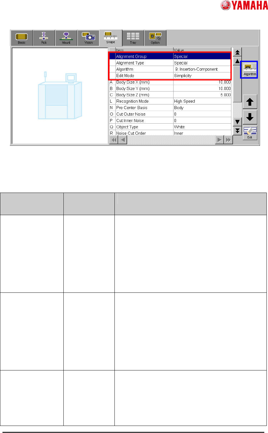
Fig.1 [Parts] – [Shape] screen
(2) Set particular parameters for “Insertion-Component” algorithm. (Ref. Table2)
Table2 Particular parameters for “Insertion-Component” algorithm
Item Range or
selection item
Explanation
Recognition Mode High Speed /
Detail
When “High Speed”, it is judged by a binary image
whether the recognized image of the pin end is
correspond to the definition shape. And, when
“Detail “, it is judged by matching processing.
Specify ”High Speed” when contrast of pin end is
clear. Specify ”Detail” when pin end is dark and
contrast does not clear.
Pin Matching Level
(%)
0~100 * Only when “Recognition Mode” is ”Detail”.
Specify the judging standard of whether the
recognized image of the pin end is correspond to
the definition shape.
When the matching level is less than this value, the
recognition error occurs.
In the case of 0%, it is treated as 50%.
Pre Center Basis Pin / Body Specify ”Pin” when the parts center position is
datum pin detection center. Specify ”Body” when
the parts center position is center of the parts body
(Calculated by the method of “Center Pre-detection
Algo”). (Ref. fig.2, fig.3)

SMT Software Engineering Group
IM Operations YAMAHA MOTOR CO., LTD.
MDOC-SOFT50229 4/12
Cut Outer Noise
Cut Inner Noise
0 / 1 / 2 / 3 / 4 /
5 / 6 / 7
* Only when “Pre Center Basis” is ”Body”.
Specify amount of noise cut.
Too large application decreases information
amount because the image is processed.
Object Type White / Black * Only when “Pre Center Basis” is ”Body”.
Specify “White” when the parts body is bright color.
Specify “Black” when the parts body is dark color.
Noise Cut Order Inner / Outer * Only when “Pre Center Basis” is ”Body”.
Specify execution sequence of noise cut.
Usually, first executed action has bigger effect.
Contour Tracing
Threshold
0~255 * Only when “Pre Center Basis” is ”Body”.
Specify threshold value of separating black and
white of outside of parts.
Adjust this value so that parts shape is recognized
clearly.
Center
Pre-detection Algo
Center Of
Gravity / Apex
Of Rectangle
* Only when “Pre Center Basis” is ”Body”.
Specify the calculation method of the parts center
position.
Specify “Center Of Gravity” when the gravity center
of the detected outline is the parts center position.
Specify “Apex Of Rectangle” when the center of the
rectangle that consists of fitting lines of each
neighborhood is the parts center position. (Ref.
fig.3)
Pin Pos Offset X
(mm)
Pin Pos Offset Y
(mm)
-99.999~99.999
* Only when “Pre Center Basis” is ”Body”.
Specify these values when you offset the pin
definition position. (Ref. fig.4)
Pin Pos Tolerance
(mm)
-99.999~99.999
Specify the permitted pin bend amount.
Pin bend judgment is performed for each pin. And
the recognition error occurs when at least one pin
exceeds this tolerance value. (Ref. fig.5)
Check Direction
Enable
Off / On Specify “On” when using direction check.
SMT Software Engineering Group
IM Operations YAMAHA MOTOR CO., LTD.
MDOC-SOFT50229 5/12
Check Type Black / White * Only when “Check Direction Enable” is ”On”.
Specify “White” when the brightness of the
specified brightness measurement area is brighter
than the brightness of the rotary symmetric
position. Specify “Black” in the case of reverse.
Check Direction 2 Angle / 4
Angle
* Only when “Check Direction Enable” is ”On”.
Specify the angle of direction check.
If the pin placement is different when parts is
rotated 90 degrees, specify “2 Angle” to judge 0
degree / 180 degree. If the pin placement is same
when parts is rotated 90 degrees / 180 degrees /
270 degrees, specify “4 Angle” to judge 0 degree /
90 degree / 180 degree / 270 degree. (Ref. fig.6)
Dir Mark Diameter
(mm)
0.010~99.999 * Only when “Check Direction Enable” is ”On”.
Specify the diameter of circular area where
brightness measurement is performed. (Ref. fig.6)
Dir Mark Center X
(mm)
Dir Mark Center Y
(mm)
-99.999~99.999
* Only when “Check Direction Enable” is ”On”.
Specify the center position of circular area where
brightness measurement is performed. Origin is
center of the parts. (Ref. fig.6)
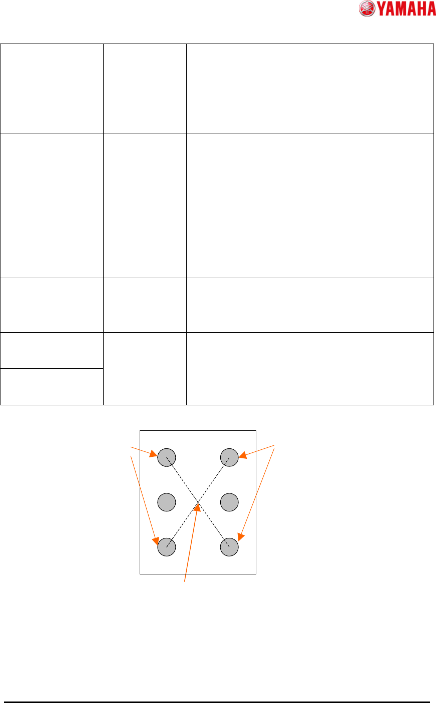
Fig.2 Parts center position when “Pre Center Basis” is “Pin”
Center of the datum pin detection position --> Parts center
Datum pins
Datum pins