TM5739.Insertion-Component_SimpleVisionAlgorithmSetting.pdf - 第6页
SMT Software En gineering G rou p IM Ope rations Y A M A HA MOTOR CO., L TD. MDO C-SOFT 50229 6/12 Fig.3 Parts ce nter position w hen “Pre Ce nter Basis” is “Body” Fig.4 Setting of “Pin Pos Of fset X, Y ” Grav…
SMT Software Engineering Group
IM Operations YAMAHA MOTOR CO., LTD.
MDOC-SOFT50229 5/12
Check Type Black / White * Only when “Check Direction Enable” is ”On”.
Specify “White” when the brightness of the
specified brightness measurement area is brighter
than the brightness of the rotary symmetric
position. Specify “Black” in the case of reverse.
Check Direction 2 Angle / 4
Angle
* Only when “Check Direction Enable” is ”On”.
Specify the angle of direction check.
If the pin placement is different when parts is
rotated 90 degrees, specify “2 Angle” to judge 0
degree / 180 degree. If the pin placement is same
when parts is rotated 90 degrees / 180 degrees /
270 degrees, specify “4 Angle” to judge 0 degree /
90 degree / 180 degree / 270 degree. (Ref. fig.6)
Dir Mark Diameter
(mm)
0.010~99.999 * Only when “Check Direction Enable” is ”On”.
Specify the diameter of circular area where
brightness measurement is performed. (Ref. fig.6)
Dir Mark Center X
(mm)
Dir Mark Center Y
(mm)
-99.999~99.999
* Only when “Check Direction Enable” is ”On”.
Specify the center position of circular area where
brightness measurement is performed. Origin is
center of the parts. (Ref. fig.6)
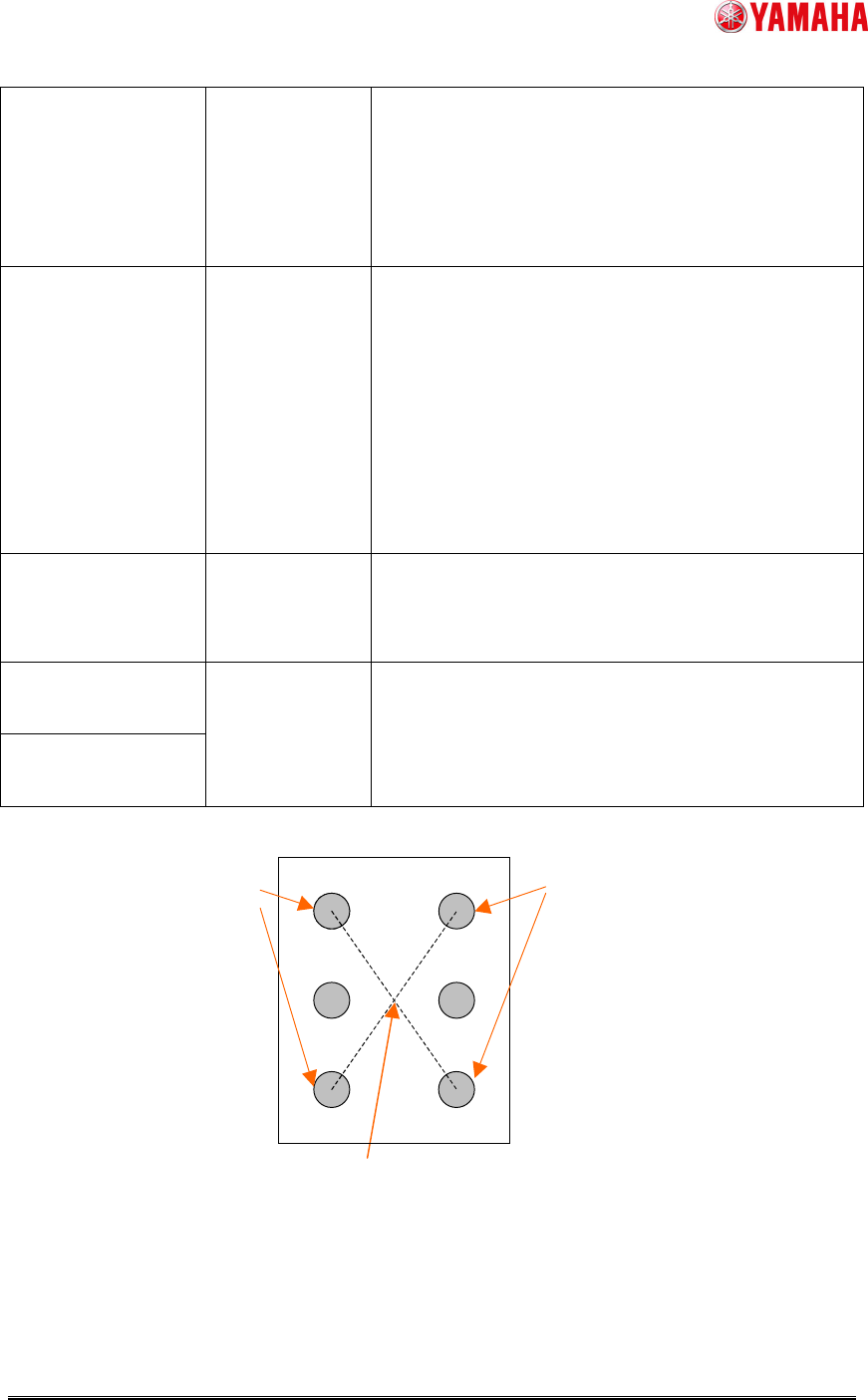
Fig.2 Parts center position when “Pre Center Basis” is “Pin”
Center of the datum pin detection position --> Parts center
Datum pins
Datum pins
SMT Software Engineering Group
IM Operations YAMAHA MOTOR CO., LTD.
MDOC-SOFT50229 6/12
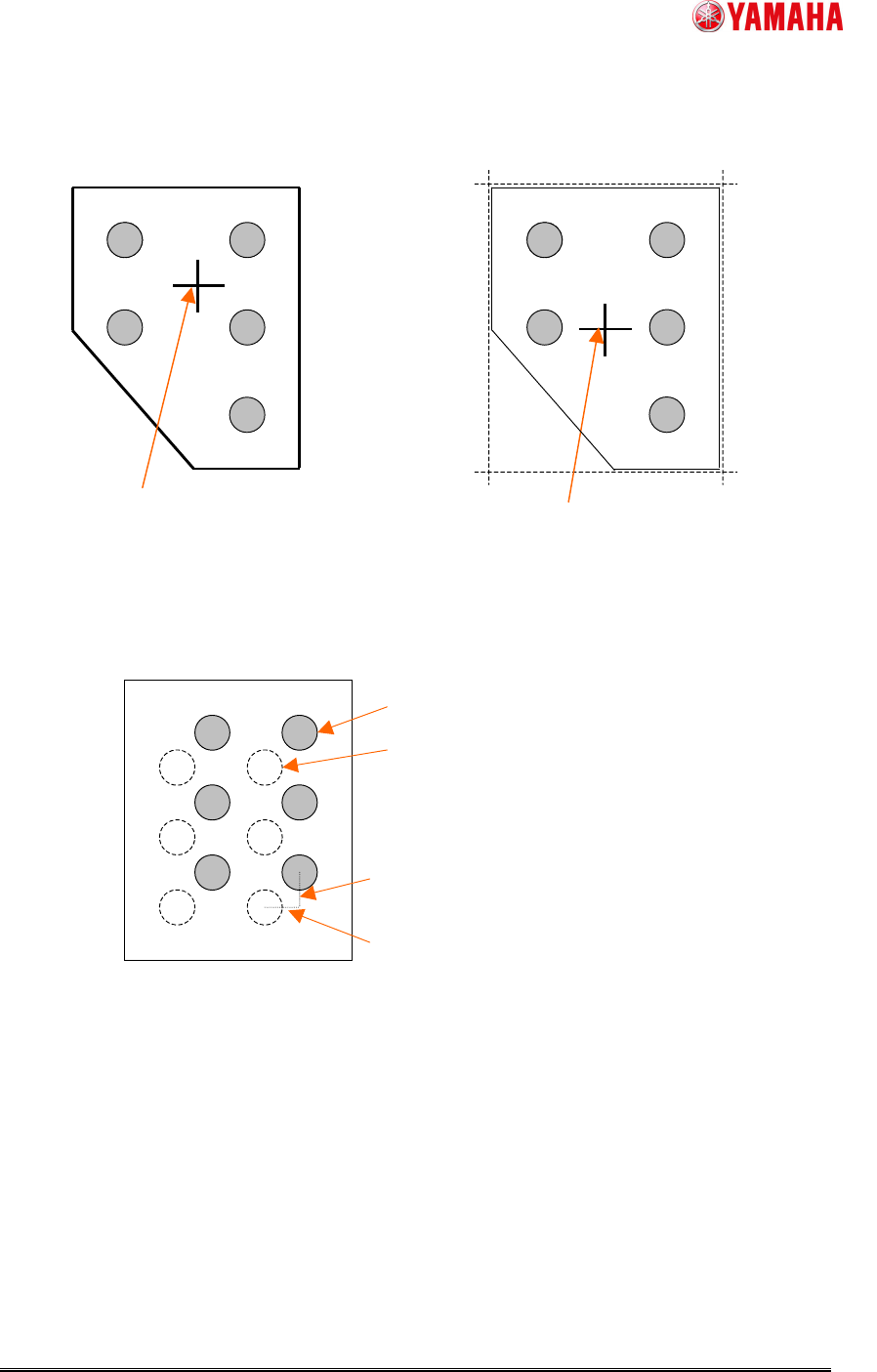
Fig.3 Parts center position when “Pre Center Basis” is “Body”
Fig.4 Setting of “Pin Pos Offset X, Y”
Gravity center of the detected outline
--> Parts center
Center of the rectangle that consists of fitting
lines of each neighborhood --> Parts center
“Pre Center Basis” is “Body”, and “Center
Pre-detection Algo” is “Center Of Gravity”
“Pre Center Basis” is “Body”, and “Center
Pre-detection Algo” is “Apex Of Rectangle”
Pin Pos Offset Y
Pin Pos Offset X
Pin definition position before offset
Pin definition position after offset
SMT Software Engineering Group
IM Operations YAMAHA MOTOR CO., LTD.
MDOC-SOFT50229 7/12
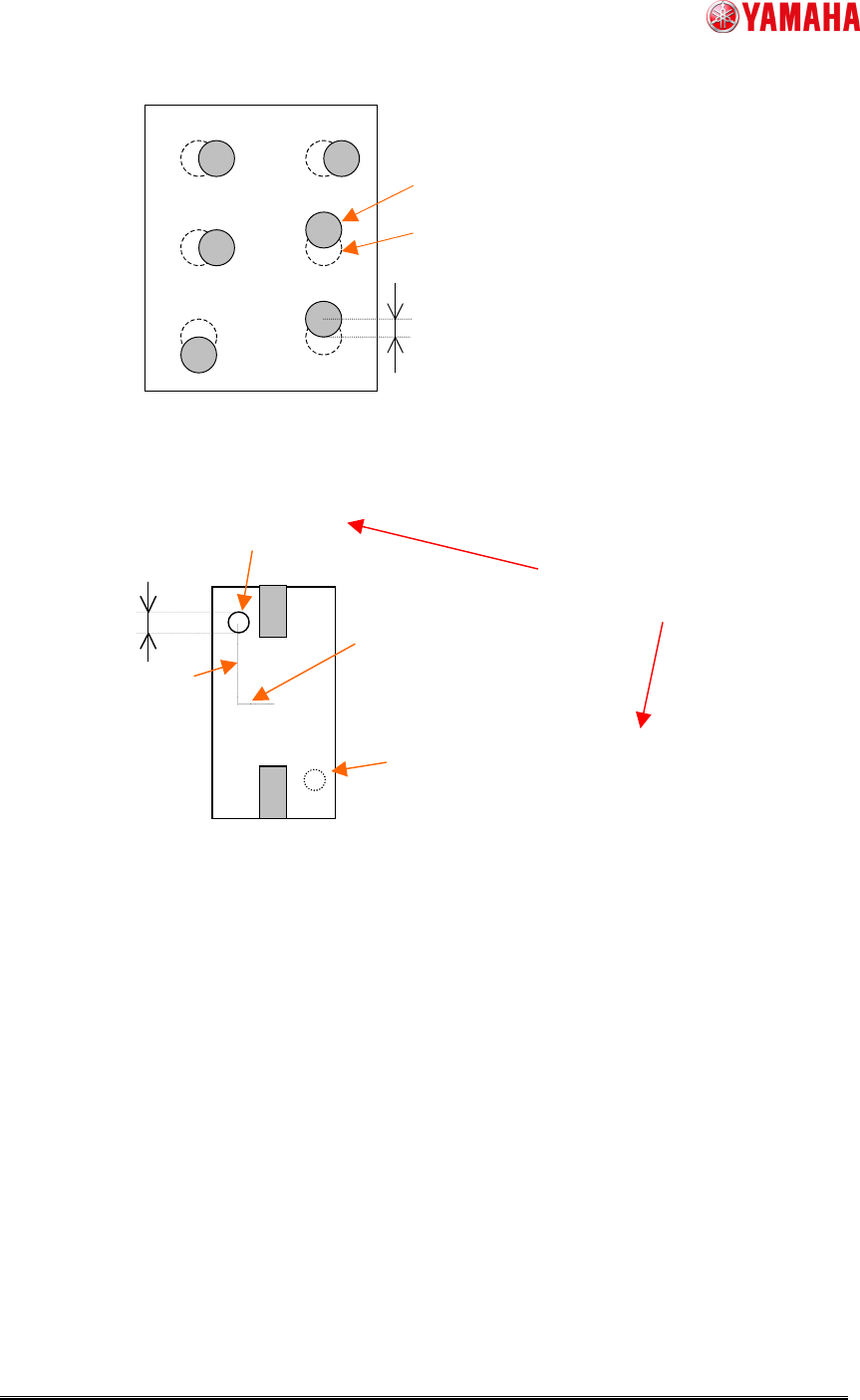
Fig.5 Setting of “Pin Pos Tolerance”
Fig.6 Setting of “Check Direction”
Detection circle
Point symmetry area around the parts
center of detection circle
(When “Check Direction” is “2 Angle”)
Compare average brightness
in both. (Check Type)
“Dir Mark
Diameter”
“Dir Mark Center Y”
“Dir Mark Center X”
Theoretical pin position
calculated by parts center
Pin detection position
Pin Pos Tolerance