TM5739.Insertion-Component_SimpleVisionAlgorithmSetting.pdf - 第9页
SMT Software En gineering G rou p IM Ope rations Y A M A HA MOTOR CO., L TD. MDO C-SOFT 50229 9/12 In editor , tap [Edit] - [Pin Posi tio n Edit] of menu (Or , ”Pin Position E dit” button at toolbar) and open ”P…
SMT Software Engineering Group
IM Operations YAMAHA MOTOR CO., LTD.
MDOC-SOFT50229 8/12
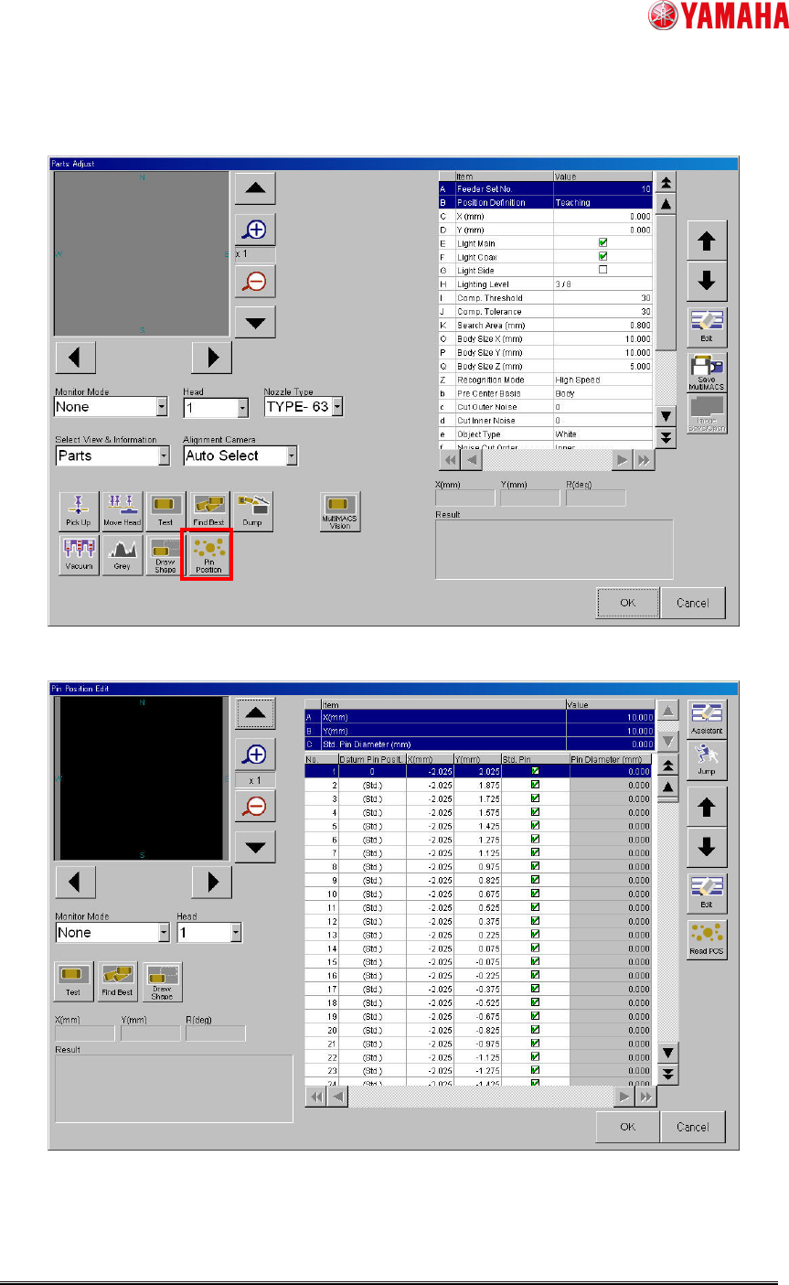
(3) Tap [Parts] - [PartsAdj] - [Pin Position] button and open ”Pin Position Edit” screen, and
set pin position data.
Fig.7 [Parts] – [Parts Adj] screen
Fig.8 [Parts] - [Parts Adj] - [Pin Position Edit] screen
SMT Software Engineering Group
IM Operations YAMAHA MOTOR CO., LTD.
MDOC-SOFT50229 9/12
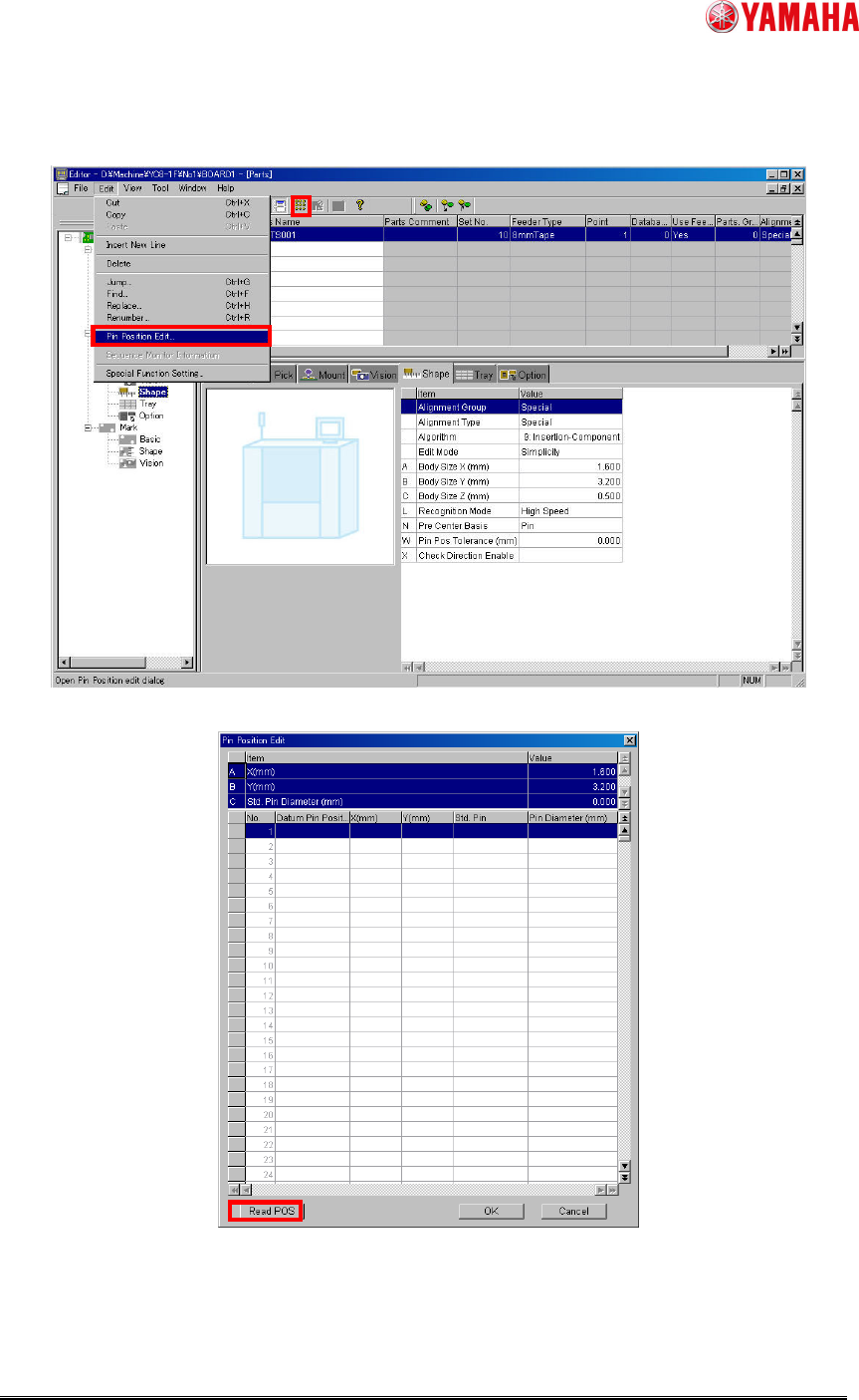
In editor, tap [Edit] - [Pin Position Edit] of menu (Or, ”Pin Position Edit” button at toolbar)
and open ”Pin Position Edit” screen.
Fig.9 Editor
Fig.10 [Pin Position Edit] screen of editor
SMT Software Engineering Group
IM Operations YAMAHA MOTOR CO., LTD.
MDOC-SOFT50229 10/12
Set following values to the upper column of [Pin Position Edit] screen.
Item Explanation
X (mm), Y (mm) Input parts size.
Std. Pin Diameter (mm) Input pin size.
Set each pin position data to the lower column of [Pin Position Edit] screen.
Item Explanation
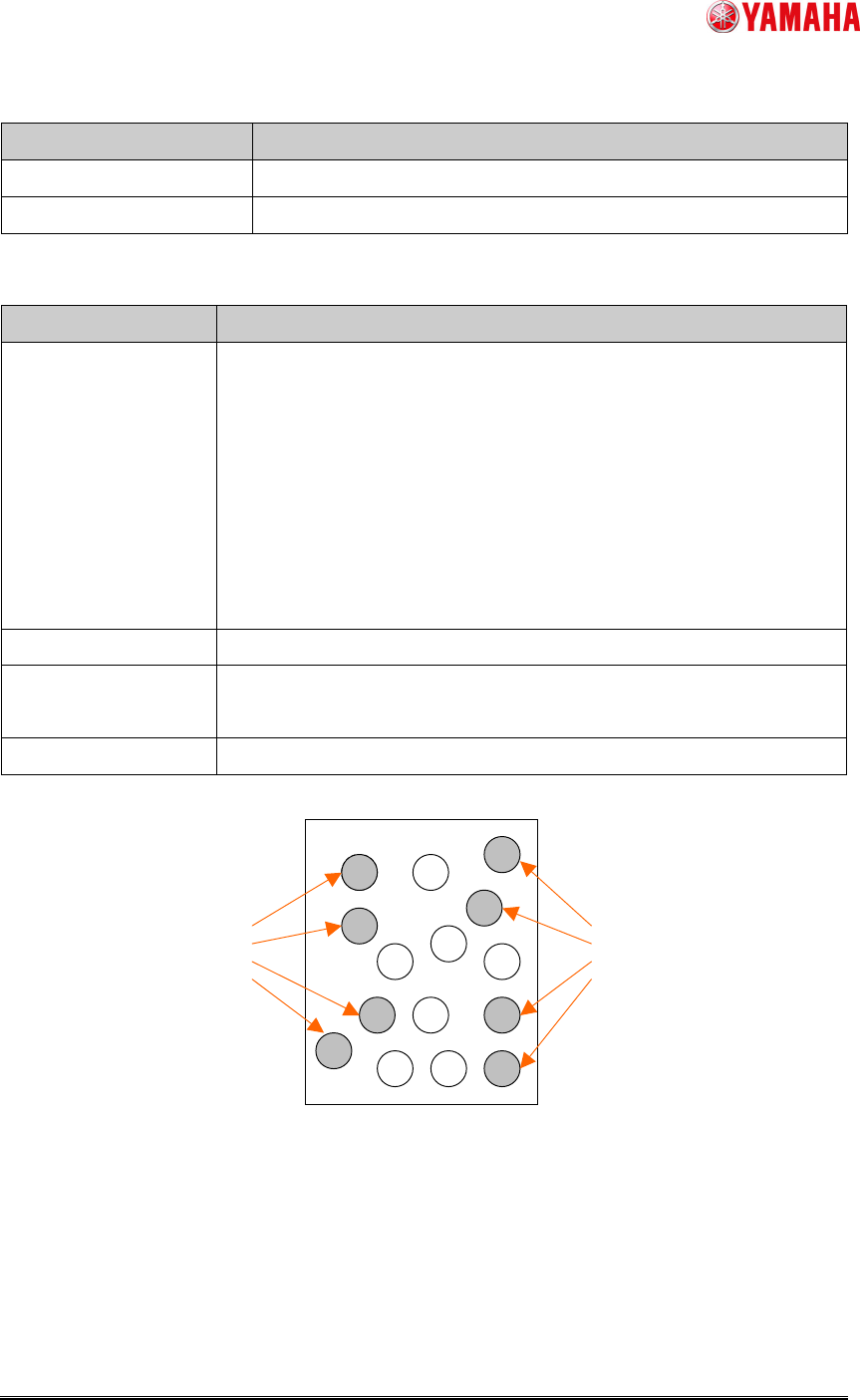
Datum Pin Position
Choose the pins located preferably outside as datum pins in each
position of the upper left, the upper right, the lower left, and the
lower right. And allocate number “0” ~ “7” to them. (Ref. fig.11)
The datum pins are required two or more pairs. When parts have
only three or less pins, add same X and Y coordinate data
(“Datum pin position” number is not overlapping) to two or more
lines.
Set “(Std.)” except datum pins.
X (mm), Y (mm) Please input the coordinates from parts center.
Std. Pin
When check is attached, “Std. Pin Diameter” of upper column is
applied.
Pin Diameter (mm) When “Std. Pin” is unchecked, input pin diameter.
Fig.11 Datum pin position
Datum pin
Datum pin