TM5739.Insertion-Component_SimpleVisionAlgorithmSetting.pdf - 第7页
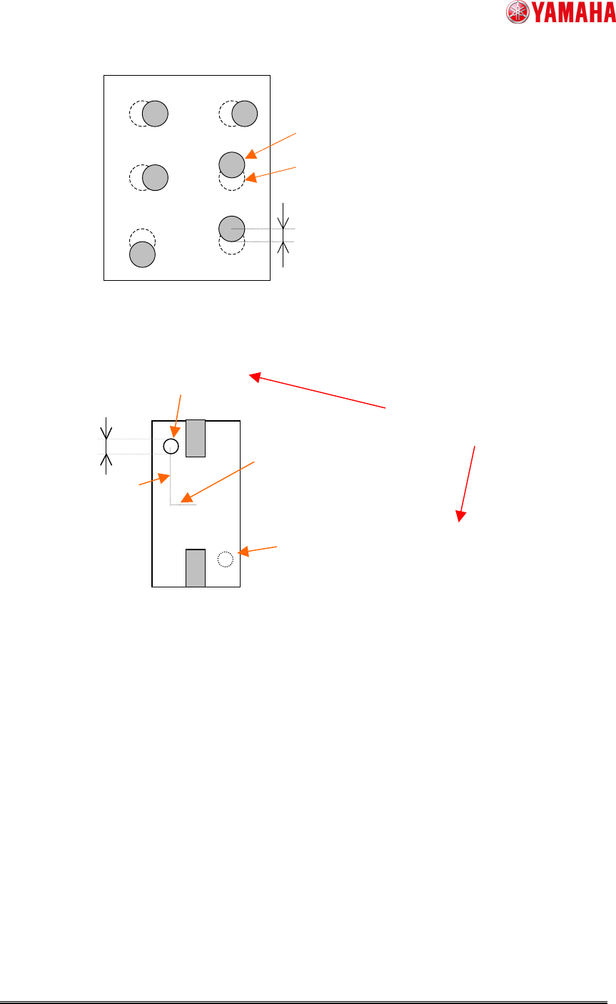
SMT Software En gineering G rou p IM Ope rations Y A M A HA MOTOR CO., L TD. MDO C-SOFT 50229 7/12 Fig.5 Setting of “Pin Pos T olerance” Fig.6 Setting of “Chec k Direction ” Detection circle Point symmetry area …
SMT Software Engineering Group
IM Operations YAMAHA MOTOR CO., LTD.
MDOC-SOFT50229 6/12
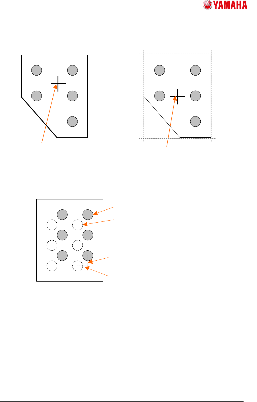
Fig.3 Parts center position when “Pre Center Basis” is “Body”
Fig.4 Setting of “Pin Pos Offset X, Y”
Gravity center of the detected outline
--> Parts center
Center of the rectangle that consists of fitting
lines of each neighborhood --> Parts center
“Pre Center Basis” is “Body”, and “Center
Pre-detection Algo” is “Center Of Gravity”
“Pre Center Basis” is “Body”, and “Center
Pre-detection Algo” is “Apex Of Rectangle”
Pin Pos Offset Y
Pin Pos Offset X
Pin definition position before offset
Pin definition position after offset
SMT Software Engineering Group
IM Operations YAMAHA MOTOR CO., LTD.
MDOC-SOFT50229 7/12
Fig.5 Setting of “Pin Pos Tolerance”
Fig.6 Setting of “Check Direction”
Detection circle
Point symmetry area around the parts
center of detection circle
(When “Check Direction” is “2 Angle”)
Compare average brightness
in both. (Check Type)
“Dir Mark
Diameter”
“Dir Mark Center Y”
“Dir Mark Center X”
Theoretical pin position
calculated by parts center
Pin detection position
Pin Pos Tolerance
SMT Software Engineering Group
IM Operations YAMAHA MOTOR CO., LTD.
MDOC-SOFT50229 8/12
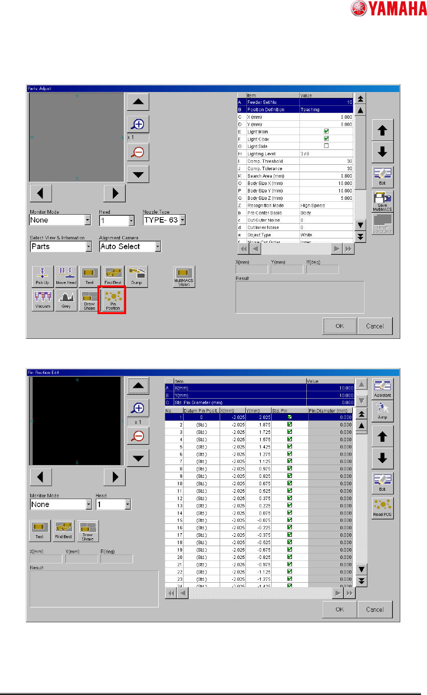
(3) Tap [Parts] - [PartsAdj] - [Pin Position] button and open ”Pin Position Edit” screen, and
set pin position data.
Fig.7 [Parts] – [Parts Adj] screen
Fig.8 [Parts] - [Parts Adj] - [Pin Position Edit] screen