05_SM481_Service Manual Conveyor.pdf - 第11页
Conveyor 5-7 4. A ss em ble t he belt in t he reverse orde r of disassem b l ing. 5.2.5. Entry / Exit PCB T ransfer Belt replace m en t procedure 1. Remove t he timing b el t by sligh t l y loo sening the idler . 2. Re p…
Advanced High Speed Flexible Mounter
5-6
4. Assemble the belt in the reverse order of disassembling.
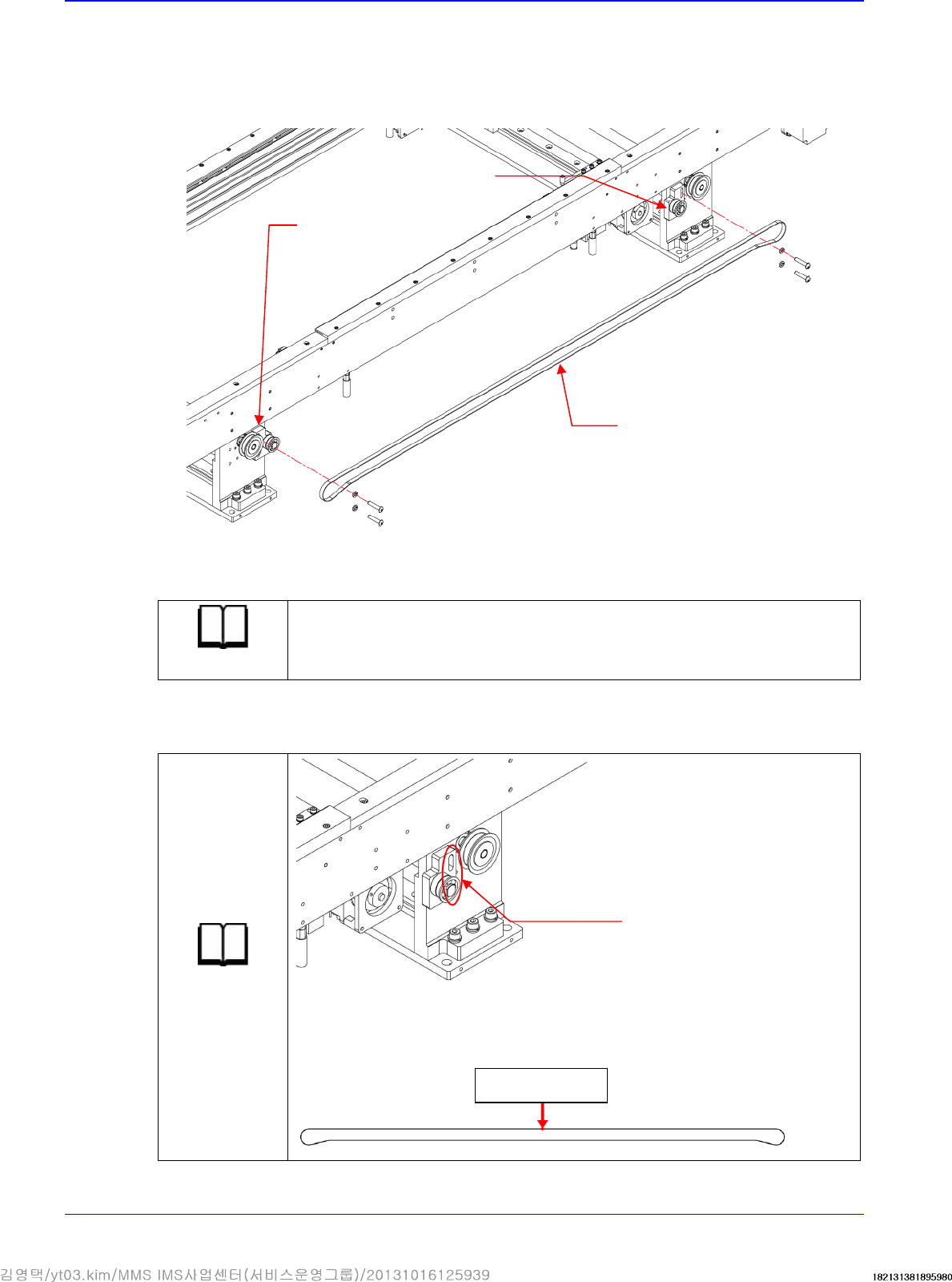
5.2.4. Manual width adjustment Belt replacement procedure
1. Remove the timing belt by slightly loosening the fixing screws of the Bracket-Servo Motor.
2. Replace the belt with a new one.
Reference
The part number of the new belt is J6602074A
3. When assembling the timing belt after it has been replaced, set the timing belt tension by using
the space of the hole on the Bracket-Servo Motor by referring to the specified timing belt.
Reference
Tension : 18.5±10%Hz
Tension Gage : U-505
Servo Motor Bracket
Servo Motor Bracket
Manual width
adjustment belt
Hole
Measurement
position
Conveyor
5-7
4. Assemble the belt in the reverse order of disassembling.
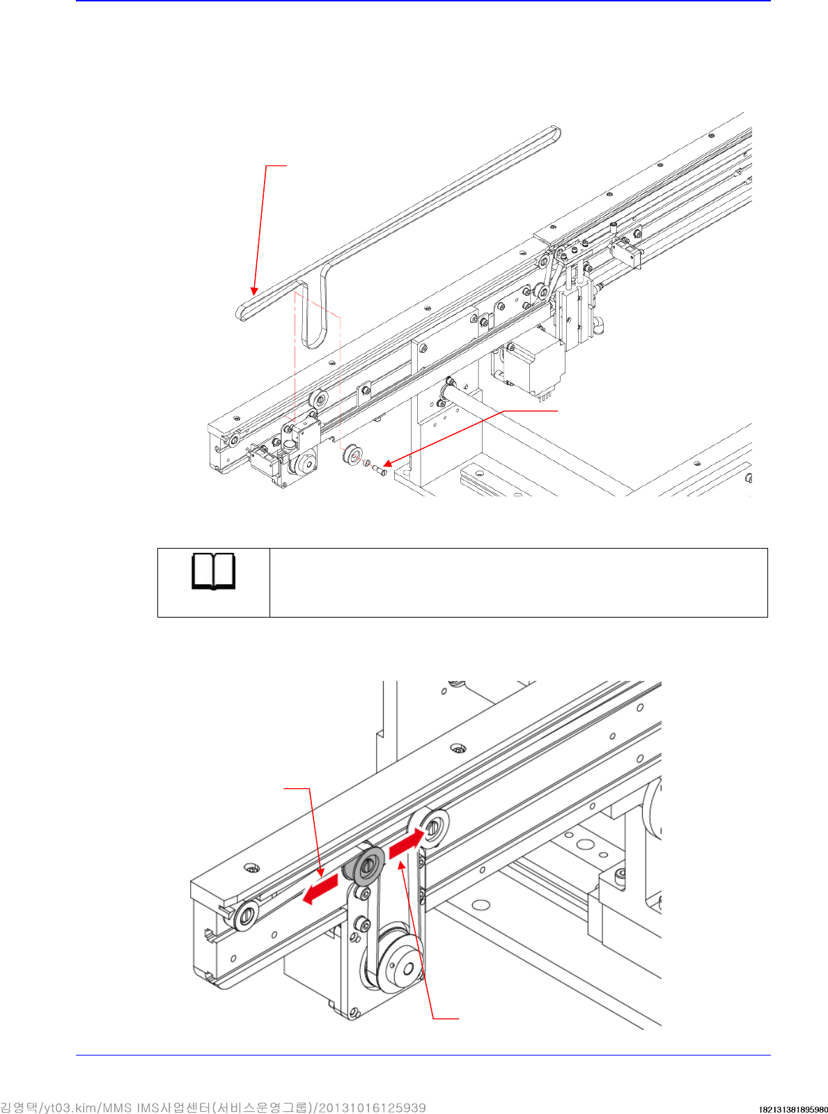
5.2.5. Entry / Exit PCB Transfer Belt replacement procedure
1. Remove the timing belt by slightly loosening the idler.
2. Replace the belt with a new one.
Reference
The part number of the new belt is J66021017A
3. By adjusting the belt tension using a screw driver with a ‘-’ shaped tip, move the idler shaft to
the left and right through the conveyor frame rail and then adjust the tension.
Idler Shaft
Belt
Increase in the PCB
transfer belt tension
Reduction of PCB
transfer belt tension
Advanced High Speed Flexible Mounter
5-8
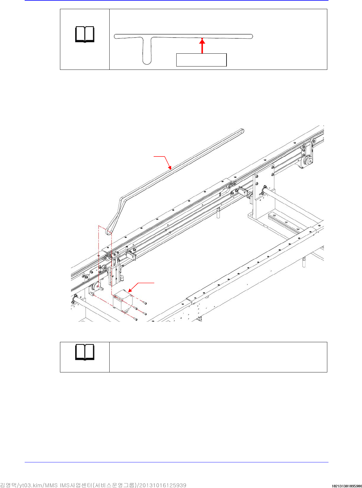
Reference
Tension : 135±10%Hz
Tension Gage : U-505
4. Assemble the belt in the reverse order of disassembling.
5.2.6. Work PCB Transfer Belt replacement procedure
1. Unscrew the fixing bolts securing the work PCB transfer belt using a hex wrench and remove
it.
2. Replace the belt with a new one.
Reference
The part number of the new belt is J66021018A
Measurement
position
Motor
Work PCB transfer