05_SM481_Service Manual Conveyor.pdf - 第6页
在线预览 05_SM481_Service Manual Conveyor.pdf PDF 文档。

Table of Contents
5-1
Table of Contents
Main Contents
Table of Contents ................................................................................................ 5-1
Main Contents ................................................................................................ 5-1
Chapter 5. conveyor ................................................................................................ 5-3
5.1. Sensor ................................................................................................ 5-3
5.1.1. Required Tools ........................................................................................ 5-3
5.1.2. Common works for sensor replacement.................................................. 5-3
5.2. Timing Belt ............................................................................................. 5-4
5.2.1. Required Tools ........................................................................................ 5-4
5.2.2. Common works for Belt replacement ...................................................... 5-4
5.2.3. Automatic width adjustment Belt replacement procedure ........................ 5-5
5.2.4. Manual width adjustment Belt replacement procedure ............................ 5-6
5.2.5. Entry / Exit PCB Transfer Belt replacement procedure ............................ 5-7
5.2.6. Work PCB Transfer Belt replacement procedure .................................... 5-8
5.3. Motor .............................................................................................. 5-10
5.3.1. Required Tools ...................................................................................... 5-10
5.3.2. Width Adjustment Motor replacement procedure .................................. 5-10
5.3.3. Entry / Exit PCB Tranfer Motor replacement procedure ........................ 5-12
5.3.4. Work PCB Tranfer Motor replacement procedure ................................. 5-13

Conveyor
5-3
Chapter 5. conveyor
5.1. Sensor
5.1.1. Required Tools
Precision screw driver set (other supplied tools)
T wrench (other tools supplied) or hex wrench
+ shape tipped screw driver set
Nipper and cable tie
5.1.2. Common works for sensor replacement
1. Manipulate the teaching box to move the X-Frame to the rear side.
2. Turn Off the PC in normal way. Then turn off the main switch on the front side of the machine.
3. Remove the sensor cable.
4. Unscrew the fixing bolts securing the sensor using a hex wrench and remove it
5. Replace the sensor with a new one.
Reference
The part number of the
new
entry, quick load sensor
is
J3211032A
The part number of the new wait, place, outpot sensor is J3211048A
The part number of the new width home sensor is J3211048A
6. Assemble the sensor in the reverse order of disassembling.
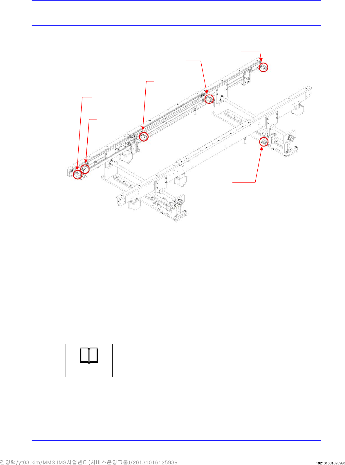
Entry Sensor
WORK ZONE
ENTRY STATION
EXIT STATION
Wait Sensor
Place Sensor
Quick Load
Sensor
Output Sensor
Width Home
Sensor