05_SM481_Service Manual Conveyor.pdf - 第14页
Advance d High Speed Flex i ble Mounter 5-10 5.3. Motor 5.3.1. Require d T ool s T e n s ion Gage(U-505) T wre nch (other tool s supplied) o r he x w r ench - shape tipped screw driver set Calipe rs 5.3.2. Width …
Conveyor
5-9
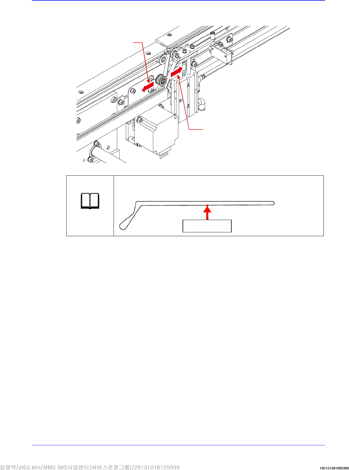
3. By adjusting the belt tension using a screw driver with a ‘-’ shaped tip, move the idler shaft to
the left and right through the conveyor frame rail and then adjust the tension.
Reference
Tension : 177±10%Hz
Tension Gage : U-505
4. Assemble the belt in the reverse order of disassembling.
Measurement
position
Increase in the PCB
transfer belt tension
Reduction of PCB
transfer belt tension
Advanced High Speed Flexible Mounter
5-10
5.3. Motor
5.3.1. Required Tools
Tension Gage(U-505)
T wrench (other tools supplied) or hex wrench
- shape tipped screw driver set
Calipers
5.3.2. Width Adjustment Motor replacement procedure
1. Manipulate the teaching box to move the X-Frame to the rear side.
2. Turn Off the PC in normal way. Then turn off the main switch on the front side of the machine.
3. Remove the cable connected to the motor.
4. Unscrew the fixing bolts securing the motor using a hex wrench and remove it.
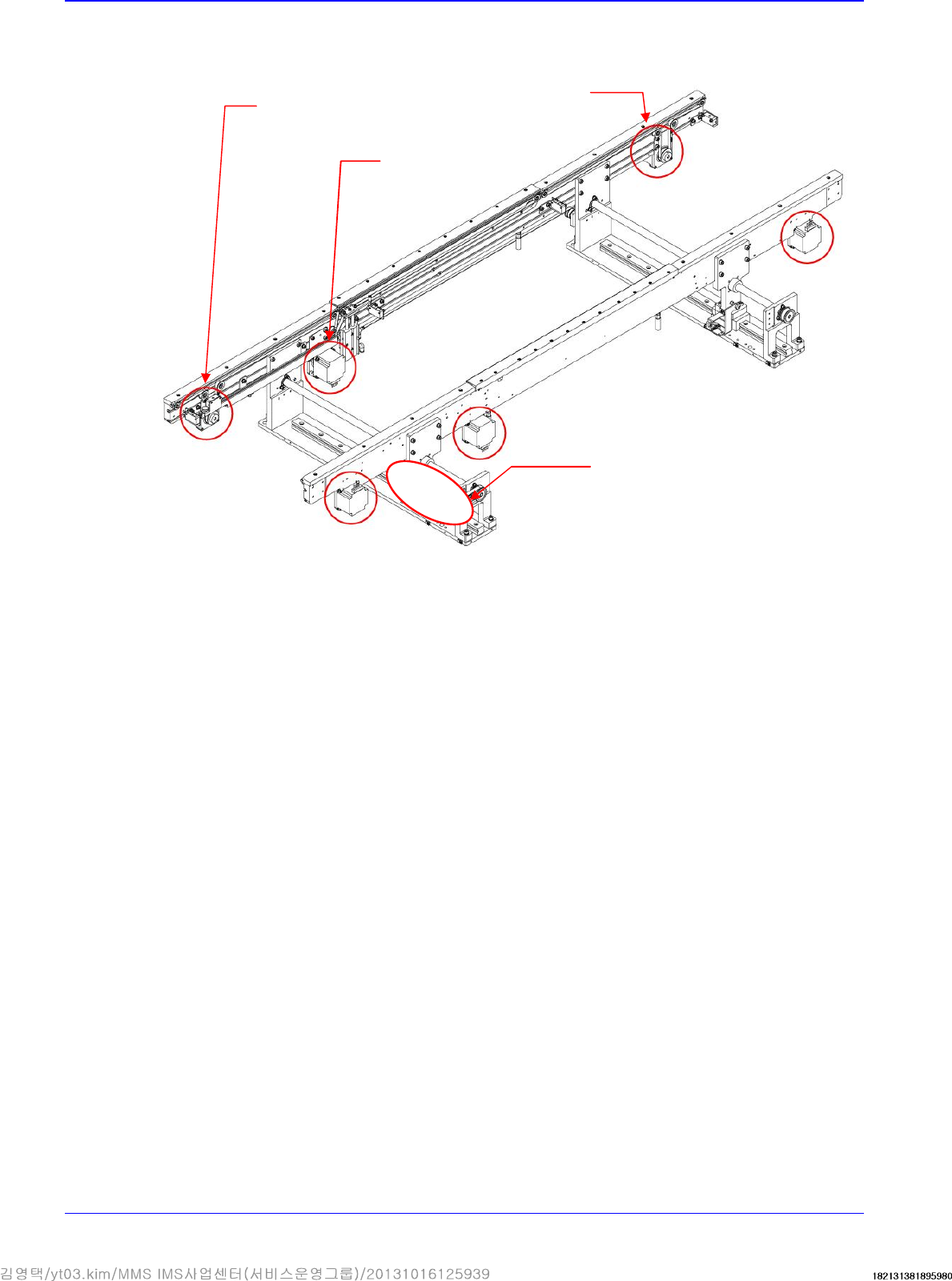
WORK ZONE
ENTRY STATION
EXIT STATION
Entry PCB
Transfer Motor
Exit PCB
Transfer
Motor
Width Adjustment Motor
Work PCB
Transfer
Motor
Conveyor
5-11
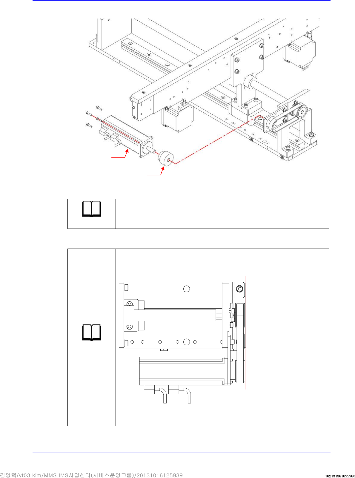
5. Unscrew the set screw securing the Pulley using a hex wrench and remove it.
6. Replace the motor with a new one.
Reference
The part number of the new motor is J3108062A
7. Assemble the motor in the reverse order of disassembling.
Reference
Basis for the motor and pulley assembling position
–
Distance from the
motor assembling surface to the pulley center.
measure its tension and compensate it by referring to "Belt replacement
procedure".
Pulley
Motor