D1_ServiceManual_e.pdf - 第15页
1 Installation 1-7 Pre-Process and Post-Process of Machine Connecting Pre-Process and Post-Process When using other manufacturer’s m achines as the pre-process or post-process, connect them as shown in the below diagram.…
1 Installation
1-6
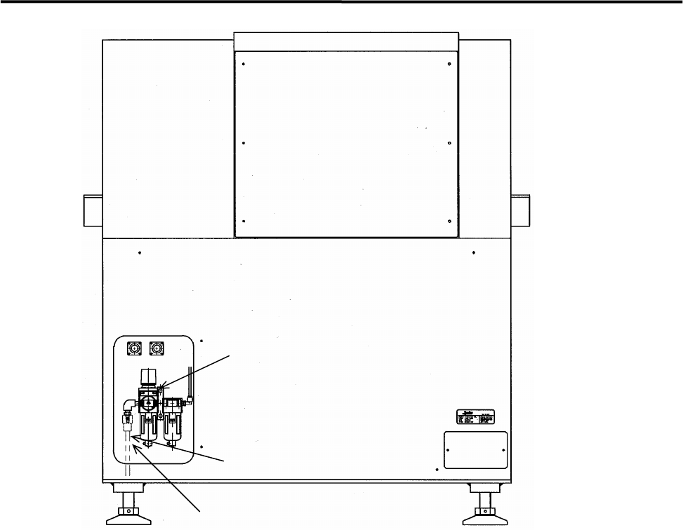
Filter Regulator
Air Coupler 65SN or 85SN
Air Coupler
1 Installation
1-7
Pre-Process and Post-Process of Machine
Connecting Pre-Process and Post-Process
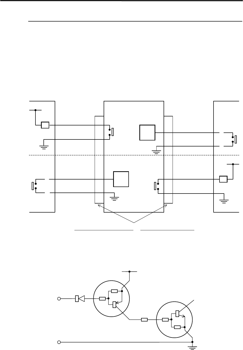
When using other manufacturer’s machines as the pre-process or post-process, connect them as shown in
the below diagram. No-voltage output (relay) is recommended for post-process.
Standard spec. : Upper half of the diagram.
SMEMA Interface spec. : Whole diagram.
* INPUT
CIRCUIT
* INPUT
CIRCUIT
2
1
CN2 CN1
Post-process
Connector (Cable side)
AMP
206044-1(plug)
66099-2 or equivalent (pin)
206070-1(cable clamp)
Connector (Machine side)
AMP
206043-1(receptacle)
Machine Pre-process
BOARD
AVAILABLE
BOARD
AVAILABLE
MACHINE
NOT READY
2.2KΩ
10KΩ
10KΩ
10KΩ
10KΩ
COM
Input
terminal
*INPUT CIRCUIT
+5V
30VDC 1A or less
100VAC 0.5A or less
RELAY
RELAY
MACHINE
NOT READY
3
4
2
1
3
4
1 Installation
1-8
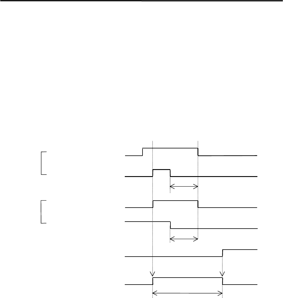
Sequence of Receiving PC board (Standard spec.)
① When the machine is ready to accept PC board, it sends out signals through MACHINE NOT READY
line to the pre-process.
② The conveyor will be activated when the entrance sensor is activated while the machine is sending out
the signals through MACHINE NOT READY line.
③ The machine stops to send out the signals through MACHINE NOT READY line after the entrance
sensor was deactivated and the time set at WAIT-1 has passed.
④ The conveyor is deactivated when the arrival sensor is activated.
⑤ If the arrival sensor will not be activated within 10 seconds after the conveyor was activated, an error
[CONVEYOR TROUBLE] will result.
⑥ Pressing START button restarts the operation paused by the error.
MACHINE NOT READY
MACHINE NOT READY
CONVEYOR
ARRIVAL SENSOR
ENTRANCE SENSOR
⑤
ON
WAIT-1
WAIT-1
OR
ENTRANCE SENSOR