D1_ServiceManual_e.pdf - 第45页
4 Electrical Section 4-5 Adjustment of Board Detection Sensors ■ Sensors z LG0-M90H3-00X PHOTO SENSOR EX-22A (SUNX) ・ Entrance Sensor ・ Exit Sensor ・ Entrance Buffer Arrival Sensor ■ Adjustment z LG0-M90H3-00X PHOTO SENS…
4 Electrical Section
4-4
Control Board
Handling Control Board
Note the followings when handling PC boards.
z Do not touch control boards by wet hands.
z Do not handle control boards where there are metal chips around.
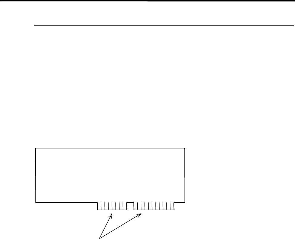
z To handle control boards in the control rack, never touch the connecting portion where gold is plated. If
the connecting portion is covered with dust, the machine doesn't work properly. Clean with alcohol.
Gold Plating
4 Electrical Section
4-5
Adjustment of Board Detection Sensors
■ Sensors
z LG0-M90H3-00X PHOTO SENSOR EX-22A (SUNX)
・ Entrance Sensor
・ Exit Sensor
・ Entrance Buffer Arrival Sensor
■ Adjustment
z LG0-M90H3-00X PHOTO SENSOR
① Place a production board on the conveyor.
② Turn the Sensitivity Adjuster fully counterclockwise to the sensitivity minimum position. (The
adjuster turns 3/4 rotation overall. If it is turned clockwise, the sensitivity increases, if turned
counterclockwise, the sensitivity decreases.)
③ Turn the Sensitivity Adjuster clockwise slowly and confirm the point “A” where the Orange LED
lights up.
④ Remove the board and continue to turn Sensitivity Adjuster clockwise and confirm the point “B”
where the Orange LED lights up. (If the sensor does not light up, just turn the adjuster clockwise to the
end.)
⑤ Turn the Sensitivity Adjuster to the center of “A” and “B”. Determine the point as a detecting point.
⑥ Put back the board on the conveyor. Be sure that the Orange LED and Green LED light up at the same
time. When you remove the board, only the Green LED should light up.
NOTE: If your machine is equipped with the CE safety conveyor cover, make sure to stick the black rubber sheet
(LG0-M9AA1-00 GOM) on the bottom surface of the cover to prevent mis-detection.
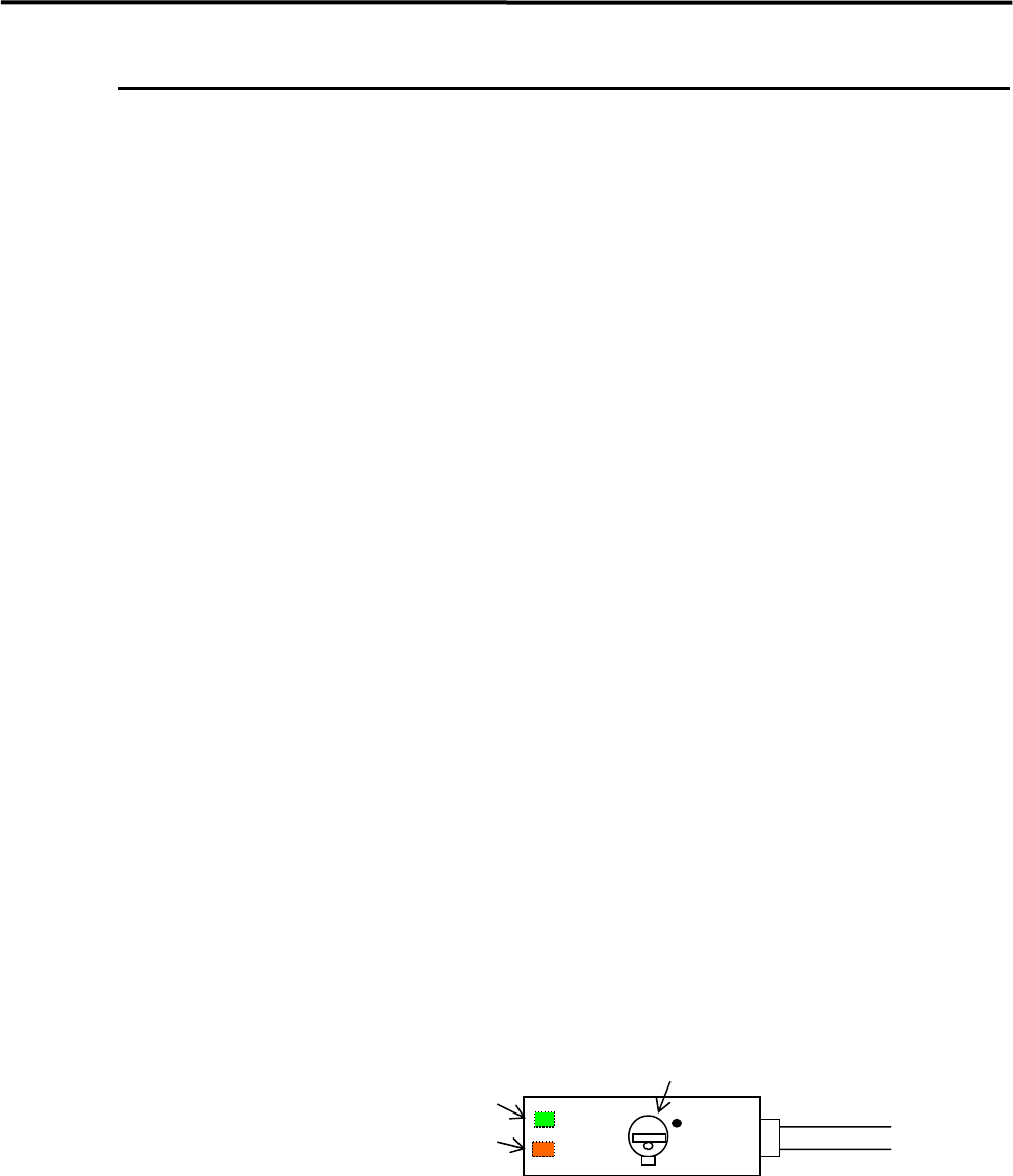
Operation Indicator (Orange LED)
(Indicators are located on the back.)
Stability Indicator (Green LED)
Sensitivity Adjuster
MAX
4 Electrical Section
4-6
● LG9-M90H6-00X PHOTO SENSOR WT4-2N112S28 (SICK)
z PCB arrival sensor
z Entrance buffer arrival sensor
■ Adjusting Method
① Use a precision flat-blade screwdriver to turn the sensitivity volume counter-clockwise as far as it will
go, to set the sensitivity to the minimum level. Place a PCB on the conveyor belt in the direction in
which PCBs will be placed for actual production operation, transfer it to a position just over the arrival
sensor, and turn the sensitivity volume clockwise until the sensor’s receiver indicator lights up.
NOTE: The sensitivity volume can be turned approx. five turns between the maximum and minimum level
positions. When the volume is beyond the maximum or minimum level position, a ratchet will be activated
and the volume turns freely with a chattering sound. The position at which such sound is heard is the limit
of the adjustable range.
② With the PCB placed on the conveyor belt, move it just above the arrival sensor back and forth a few
times by hand, to check that the receiver indicator turns ON and OFF in response to the PCB.
NOTE: The receiver indicator has three states: ON = stable operation, OFF = no sensitivity, Blink = unstable
operation. When adjusting the volume or checking sensor’s response to the PCB, make sure that the
indicator is not blinking.
③ From position (2), turn the volume 1/4 turns (90 degrees) clockwise to increase the sensitivity.
④ For verification, select [Manual] – [PCB Sensors ] to open the [PCB Sensors ] window. Check that the
PCB arrival sensor/entrance buffer arrival sensor respond to the PCB correctly. Also select [Manual]
– [Load Board ] to check that the PCB is automatically clamped properly.
NOTE: If the sensitivity is set excessively high, a malfunction may occur when the head passes over the arrival
sensor.
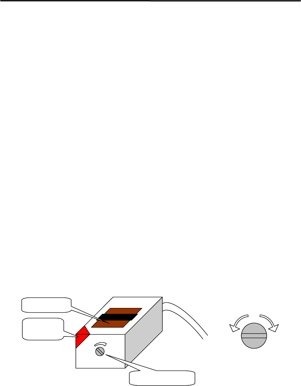
Receiver
indicator
Sensitivity Adjustment
by Volume
Higher
sensitiv
Lower
sensitiv
Sensitivity volume
Emitter/receiver