D1_ServiceManual_e.pdf - 第32页
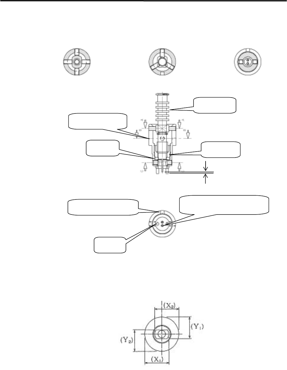
3 Mechanical Section 3-6 Section C-C Section B-B Section A-A Fig. A Fig. B Clearance U-groove for positioning ADAPTER Twin Nozzle (Be careful of the orientation) Stopper STOPPER GUIDE,NOZZLE O-ring Fig. C Fig. D
3 Mechanical Section
3-5
NOTE: Cleaning must be performed by the procedure described above. Using a wire, such as a piano wire,
damages the inner wall and the edge, and may cause stringing or side leakage.
■ How to Set Nozzle
Follow the procedure below to set a nozzle after you have disassembled the nozzle assembly for nozzle
replacement.
① Put the O-ring in the bottom of the GUIDE,NOZZLE.
② Screw in the STOPPER (TWIN,SINGLE,MICRO_S) lightly until it stops.
③ Screw in four hex. socket set screws until they show their tips inside the guide. Use
two longer screws for flat side, and two shorter screws for round side. (See Figure A)
④ Use the ADAPTER(L) for a single nozzle, and the ADAPTER(S) for twin nozzle and
micro nozzle.
⑤ Assemble the nozzle and adapter, then put them into the GUIDE,NOZZLE.
NOTE: Be careful of the orientation of the nozzle-adapter assembly, especially for a twin nozzle, when you
insert the assembly into the GUIDE,NOZZLE. See Figure C for twin nozzle orientation.
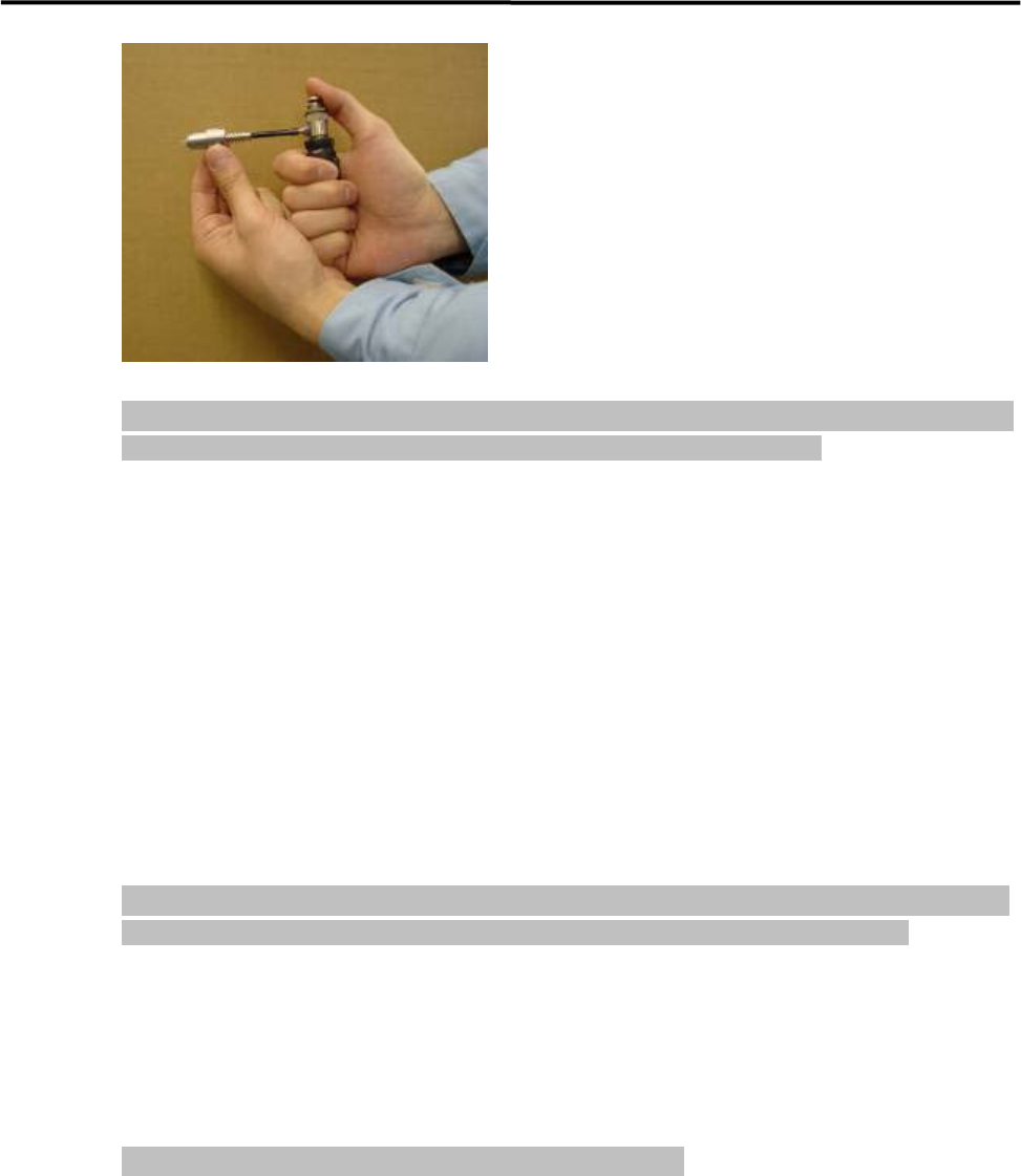
⑥ Push the nozzle-adapter assy. into the GUIDE,NOZZLE with your finger, measure
the clearance between the tips of the nozzle and stoppers using a digital vernier
caliper or a special tool.
⑦ Pull out the nozzle-adapter assy. and turn the STOPPER with a screwdriver to
adjust the clearance. The clearance must fall within ±0.015mm of the reference
clearance (one turn of the STOPPER moves it about 1mm.).
NOTE: The reference clearance differs according to the type of nozzle.
⑧ After the nozzle clearance has been adjusted, insert the nozzle-adapter assy. with
your finger, screw four hex. socket set screws until they slightly contact the nozzle.
(See Fig. A)
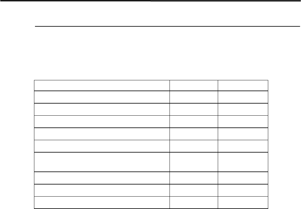
⑨ Adjust the screws so that the difference between X1 and X2, and the difference
between Y1 and Y2 will fall within 0.05mm. One turn of a screw moves it about
0.5mm. The tightening torque must be 0.15 to 0.2 N・m. (See Fig. D)
⑩ Screw three hex. socket set screws until they slightly contact the adapter. Then,
screw each set screw little by little (about 30 deg. each time) to make them equally
screwed in. The tightening torque must be 0.10 to 0.15 N・m. (See Fig. B)
3 Mechanical Section
3-6
Section C-C Section B-B Section A-A
Fig. A
Fig. B
Clearance
U-groove for positioning
ADAPTER
Twin Nozzle
(Be careful of the orientation)
Stopper
STOPPER
GUIDE,NOZZLE
O-ring
Fig. C
Fig. D
3 Mechanical Section
3-7
Lubrication
Lubrication Points
Lubricate the specified portions listed below with cotton swab soaked with lubricant.
PORTION LUBRICANT FREQ.
① Ball Screw of X-axis
Grease Monthly
② Linear Guide of X-axis
Grease Monthly
③ Ball Screw of Y-axis
Grease Monthly
④ Linear Guide of Y-axis
Grease Monthly
⑤ Conveyor Width Adjusting Liner Guide
Grease Monthly
⑥ Between Origin Dog and Bearing Block
Between Bearing Cover and Bearing Block
Grease Every two weeks
⑦ Rod Block and Sliding Part of Rod
Grease Monthly
⑧ Linear Guide of Z-axis
Grease Monthly
⑨ Spline Shaft of Z-axis
Grease Every two weeks
NOTE: Do not apply excessive grease. This may cause grease scattering when the mounter is in operation.
Especially, be careful of portion ⑥ and ⑦. Be sure to wipe off the excessive grease.