TI2018-02Int01 (006).pdf - 第3页
For internal use onl y! ASM Ass embly S ystems Singapore P te Ltd S ubject to c hange without not ice 27.07.2018 535 Yishun Industrial Park A ASM TPB2 Singapore 768775 TI2018 - 02Int01 Se it e 3 - 19 3. Final Solution 3.…
For internal use only!
ASM Assembly Systems Singapore Pte Ltd Subject to change without notice 27.07.2018
535 Yishun Industrial Park A ASM TPB2
Singapore 768775 TI2018-02Int01 Seite 2 - 19
1.3 New eSW for JTF-MW
Some of the JTF-MW in the field does not have the capability of downloading the latest firmware from
machine into the control card (part number 03116629-02).
Affected JTF-MW that need to be retrofitted are from J0001 to J0043
1.4 D1-127453301 Feeder are in an undefined state after restart of the machine & D1-125647402
Unexpected reboot during feeder eSW download
In D1-127453301, the supply voltage for FCU and feeder drops down if too many feeders start their foil
drive automatically at the same time after power ON initializing.
In D1-125647402, the supply voltage for FCU and feeder drops down after start of an eSW download
Affected on all existing FCU and Feeders.
1.5 Gantry Humming/Vibration during movement
A small number of machines in the field are exhibiting humming sound during gantry movement, and
some even up to a level of vibration.
Affected machine that need to be upgraded are from E0001 to E0242.
2. Cause
2.1 New Head Board Design with Head Board Interface Plate
Several weak spots have been identified on the current board.
2.2 New Low Voltage Fusing Board Design
The observed Electrical Over Stress (EOS) damage indicates that these failures were subjected to
overvoltage/overcurrent conditions.
2.3 New eSW for JTF-MW
The control card with part number 03116629-02 is installed with an old EPROM which result that it does
not have the function of downloading the latest embedded software from the machine to the board itself.
2.4 D1-127453301 Feeder are in an undefined state after restart of the machine & D1-125647402
Unexpected reboot during feeder eSW download
In D1-127453301, a Peak current cause a voltage drop, resulting the unidentified state of the feeders.
In D1-125647402, the defect occurs with 24-56mm (non Smart) feeders only. The control board of this
feedertype is able to enter a power down mode to save power losses. Being in this power save mode,
any request of the host forces the eSW to set the standard clock rate and to switch on the motor driver
net again. This causes a current peak due to loading the capacitors of the motor driver net.
2.5 Gantry Humming/Vibration during movement
This has been identified to be related to the stability margin of the motion control of the gantry system.
For internal use only!
ASM Assembly Systems Singapore Pte Ltd Subject to change without notice 27.07.2018
535 Yishun Industrial Park A ASM TPB2
Singapore 768775 TI2018-02Int01 Seite 3 - 19
3. Final Solution
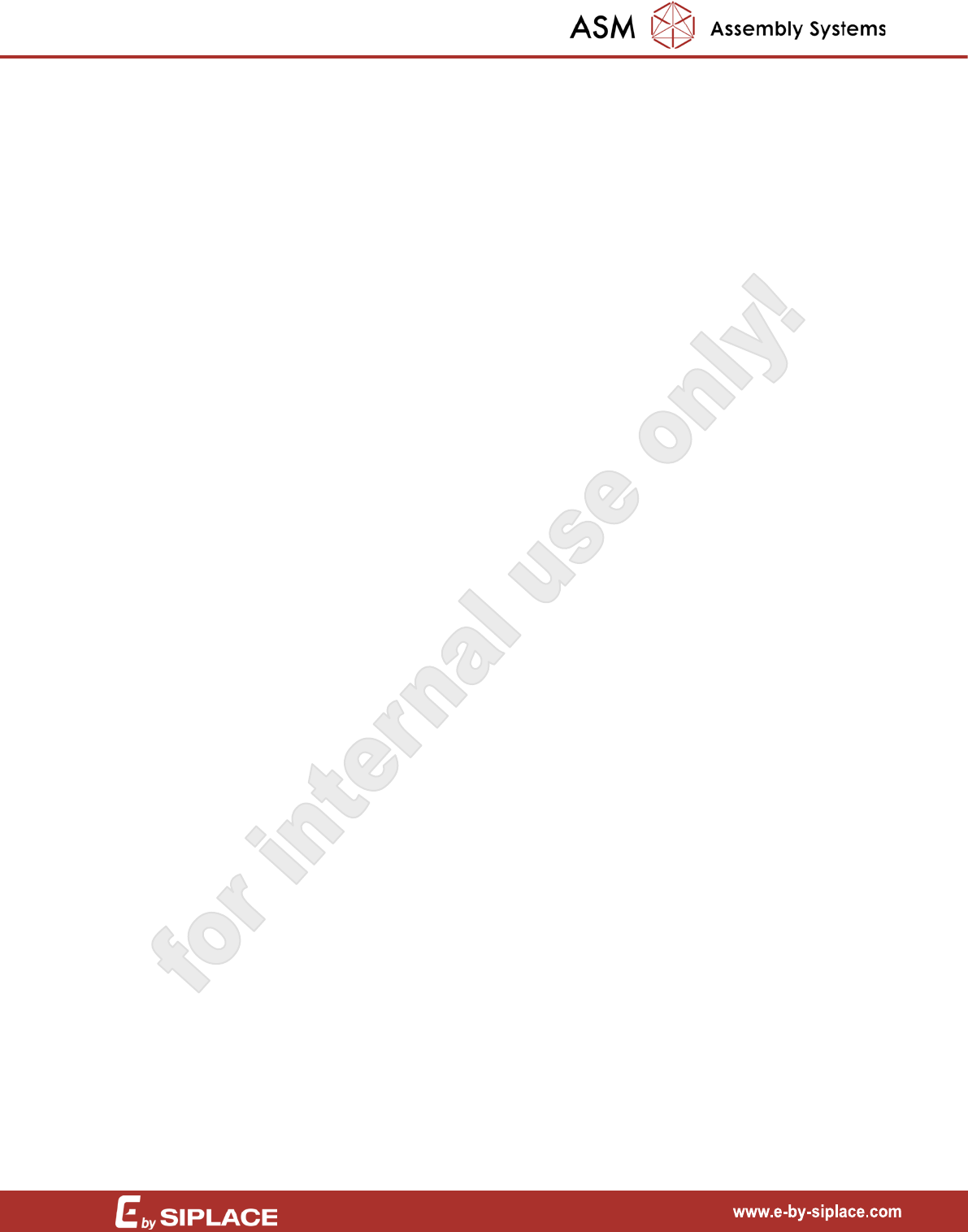
3.1 New Head Board Design with Head Board Interface Plate
The board are design to be thicker and the new interface plate has optimized strengthening supports
and additional fastening locations for the board.
3.2 New Low Voltage Fusing Board Design
Replace the Low Voltage Fusing Board from FS04 to FS05 with an improved layout of the PCB and
change the component that have better immunity to negative spike from voltage (-1V to 60V) to (-5V to
60V).
3.3 New eSW for JTF-MW
To enable the function of downloading the latest embedded software from the machine to the JTF-MW
control card. New JTF-MW control card (part Number 03117541-01) is released and have to order
together with the kit (03155561-01) for QP2 to be retrofitted for all remaining affected machine. Please
refer to TI2017-02Dis01
for the detailed information.
3.4 D1-127453301 Feeder are in an undefined state after restart of the machine & D1-125647402
Unexpected reboot during feeder eSW download
Apply station software 710.01 SP1 Hotfix04 or later version.
3.5 Gantry Humming/Vibration during movement
Apply station software 710.01 SP1 Hotfix04. Follow retrofit instruction strictly.
4. Retrofitting instructions
4.1 New Head Board Design with Head Board Interface Plate
Parts required:
03169554-xx Head Board Plate 1pc
M4 x 10mm Cap Screws 6pcs
M3 x 10mm Cap Screws 6pcs
M3 x 30mm Cap Screws 2pcs
M3 x 50mm Cap Screws 2pcs
M3 x 40mm Standoffs 7pcs
M3 x 5mm Button Head Screws 7pcs
03163875-xx PCBA Head Interface DLM+TH2 E-series 1pc
or
03164654-xx PCBA Head Interface DLM E-series 1pc
Note: Locitite 243 is not provided and required self-purchase
locally.
For internal use only!
ASM Assembly Systems Singapore Pte Ltd Subject to change without notice 27.07.2018
535 Yishun Industrial Park A ASM TPB2
Singapore 768775 TI2018-02Int01 Seite 4 - 19
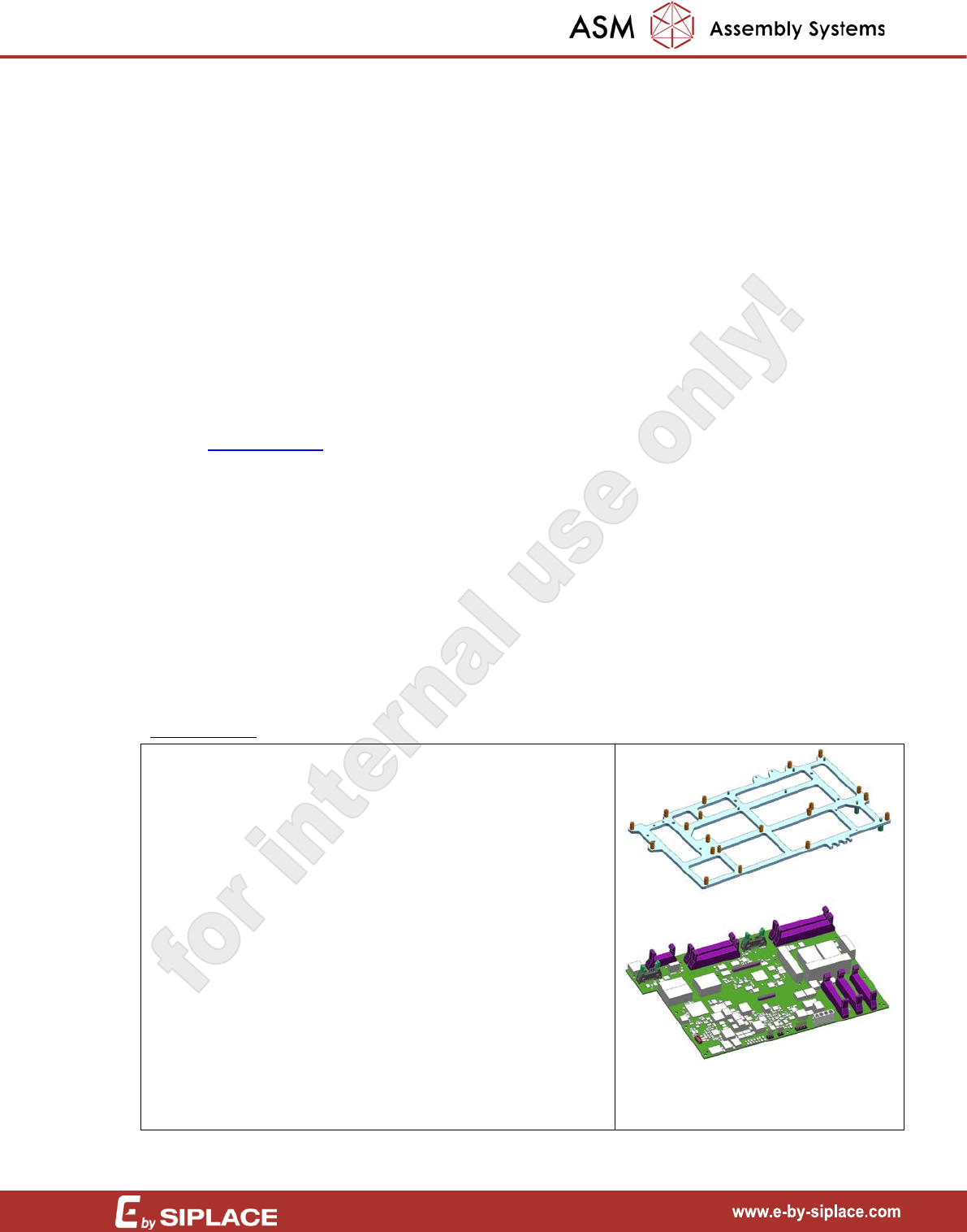
** If the machine is Flex Configuration, DLM/PP
• Power off machine
• Remove the Head board cover via loosen
the screws
• Remove the head board via removing the
standoffs/screws (between head board and
head board cover)
• Remove the VHI board via removing the
standoffs/screws (between VHI and head
board cover)
** If the machine is Speed DLM Configuration
• Power off machine
• Remove the Head board cover via loosen
the screws
• Remove the head board via removing the
standoffs/screws (between head board and
head board cover)
• Remove the VHI board via removing the
standoffs/screws (between VHI and head
board cover)
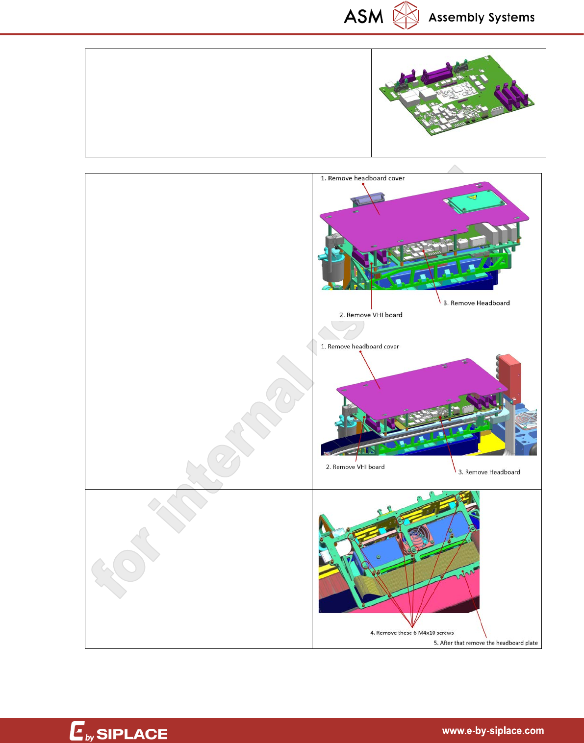
Or
• Remove the head board plate via removing
the 6pcs of M4x10 screws