M4serviceManual_e.pdf - 第16页
1 Installation 1-8 ④ After the machine is adjust ed level, check again that the transfer height is correct, and then lock each adjust foot nut. NOTE: The adjust foot nuts m ust be locked with a closed wrench (nominal: 46…
1 Installation
1-7
ACTION:
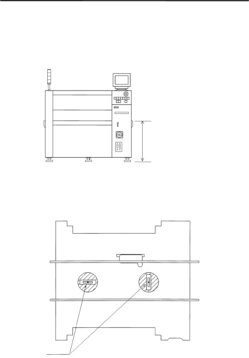
① Locate the machine to the specified place.
② Turn the adjust feet so that the PCB transfer height is the same as the conveyor height (900±20mm
(see Note)) of the reference equipment. In the case of SMEMA interface spec, the height must be 950
±20mm.
900+/-20mm
or
950+/-20mm(SMEMA)
NOTE: The height must be 890 to 920mm in the case of CFB wagon spec.
NOTE: The adjust feet must be turned using a M30 single-head wrench (nominal: 46mm).
③ Place a level on the conveyor and adjust the height so that the machine is level lengthwise and
crosswise.
Level
1 Installation
1-8
④ After the machine is adjusted level, check again that the transfer height is correct, and then lock each
adjust foot nut.
NOTE: The adjust foot nuts must be locked with a closed wrench (nominal: 46mm).
⑤ The head assy. is fixed to the XY shafts with nylon ties. Take them off with nippers.
⑥ Connect the power cable and ground line independently of other machines which may be a noise
source, such as a compressor, welding machine.
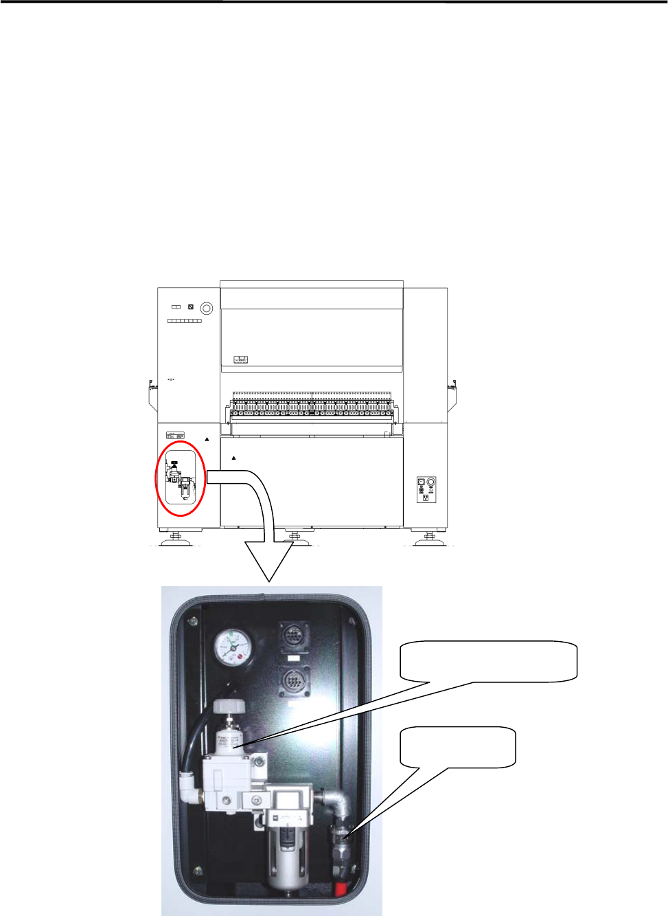
⑦ Connect an intake-side air coupler 65SN or 85SN (Nitto Kohki) or equivalent to the air regulator
coupler located on the rear of the machine. After the coupler is connected, make sure that the air
regulator’s reading is 0.5MPa(5.1 ㎏ f/c ㎡).
Intake-side air coupler
65SN/85SN (Nitto Kohki) or equivalent
Air regulator
Air coupler
1 Installation
1-9
Supplementary Explanation for Installation
When setting up a production line, level adjustment and line positioning of the machine may be carried out
at the same time. However, to fine-adjust the machine position with the machine level, i-PULSE
recommends that the machine be roughly positioned to the production line first, and then be leveled and
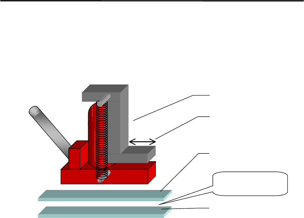
positioned accurately using the following four sets comprising a hydraulic jack and plates.
ACTION:
① Apply grease between base plates 1 and 2 for lubrication purposes.
② Place a plate set near each machine jack-up point (four points).
③ Place a jack on each plate set and jack up the machine.
④ Adjust each jack so that the machine is level.
⑤ Fine-adjust the position of the machine while the machine is jacked up. (The machine can be moved
lengthwise and crosswise with help of grease applied between the plates.)
Hydraulic jack
Base plate 1
Base plate 2
Apply grease
between the
p
lates.
Hook stroke