M4serviceManual_e.pdf - 第19页
1 Installation 1-11 Connecting Loader with Machine There is an entrance sensor at the entrance of the machine. If the loader is installed upstream of the machine, the entrance sensor m ust be moved to avoid int erruption…
1 Installation
1-10
NOTE: The machine cover must be removed while jacking up the machine
NOTE: The hydraulic jacks must satisfy the following requirements.
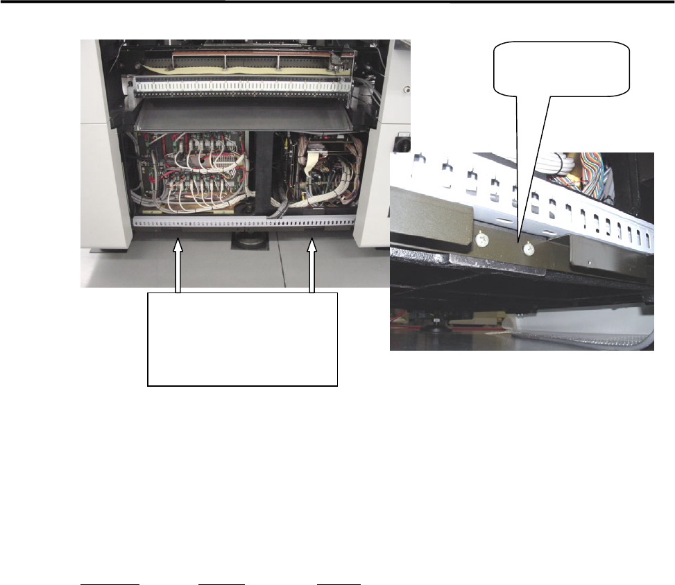
Allowable load: 1.5 tons or higher
Hook size: 100mm or more (stroke)
Part Name
Part No. Remark
PLATE,BASE LG0-M8911-00X For plates 1 and 2
Jack-up point
(enlarged view)
Jack-up point
Four points (two each at
front and rear)
1 Installation
1-11
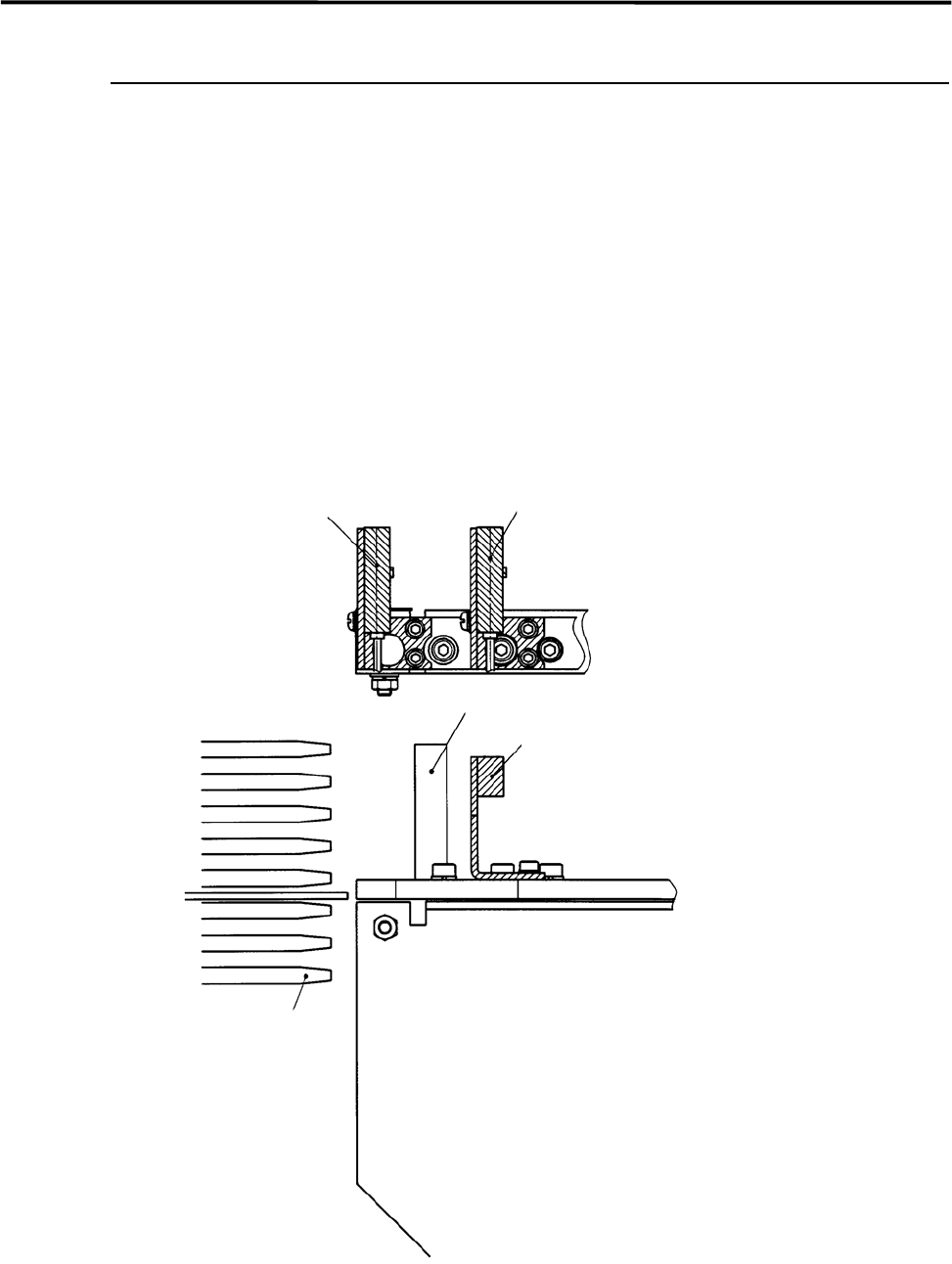
Connecting Loader with Machine
There is an entrance sensor at the entrance of the machine. If the loader is installed upstream of the
machine, the entrance sensor must be moved to avoid interruption with the loader.
After the sensor has been moved, align the conveyors for smooth board transfer.
NOTE: While moving a sensor and aligning conveyors, the power to the machine must be turned off.
a: The sensor position without a loader.
b: The sensor position with a loader installed upstream of the machine.
Loader rack
Loader’s frame
Normal position
Entrance Sensor
Position with loader installed
1 Installation
1-12
Pre-Process and Post-Process of Machine
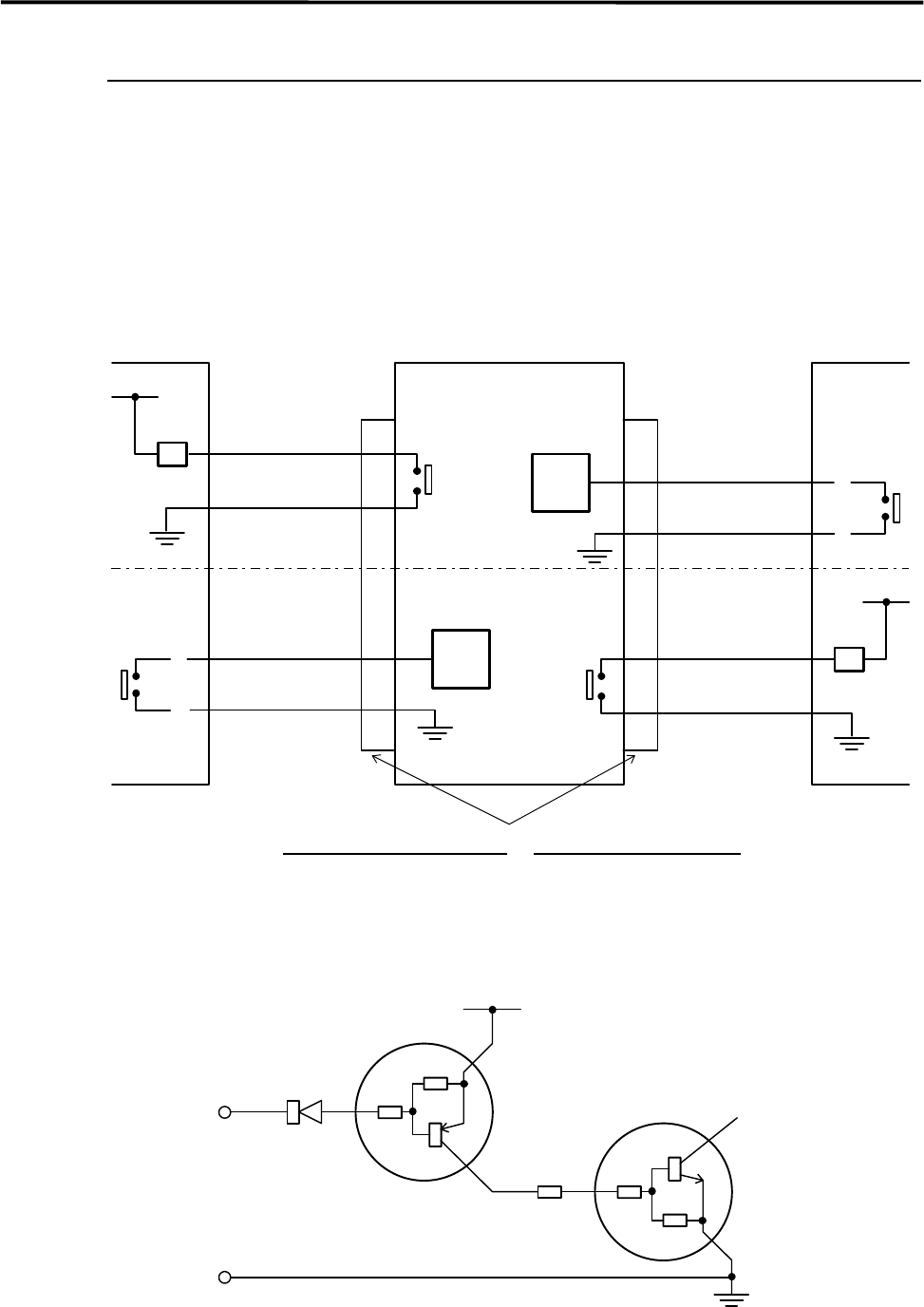
Connecting Pre-Process and Post-Process
When using other manufacturer’s machines as the pre-process or post-process, connect them as shown in
the below diagram. No-voltage output (relay) is recommended for post-process.
Standard spec. : Upper half of the diagram.
SMEMA Interface spec. : Whole diagram.
*INPUT CIRCUIT
*INPUT CIRCUIT
2
1
CN2 CN1
Post-process
Connector (Cable side)
AMP
206044-1(plug)
66099-2 or equivalent (pin)
206070-1(cable clamp)
Connector (Mounter side)
AMP
206043-1(receptacle)
MounterPre-process
BOARD
AVAILABLE
BOARD
AVAILABLE
MACHINE
NOT READY
2.2K Ω
10K Ω
10K Ω
10K Ω
10K Ω
COM
Input
terminal
*INPUT CIRCUIT
+5V
30VDC 1A or less
100VAC 0.5A or less
RELAY
RELAY
MACHINE
NOT READY
3
4
2
1
3
4