46230813.pdf - 第14页
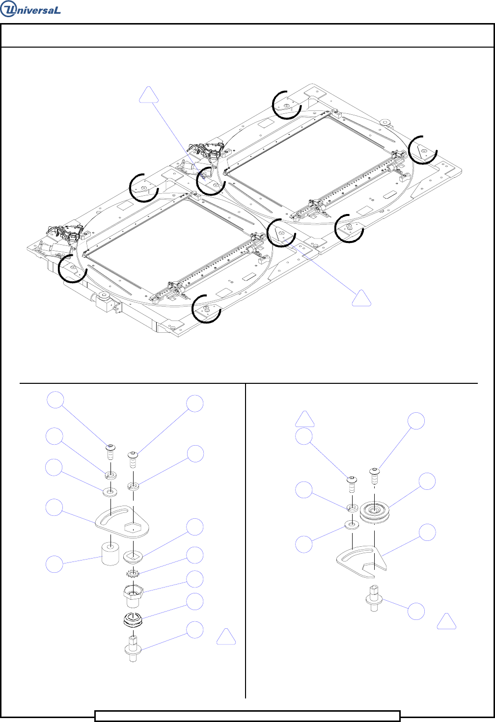
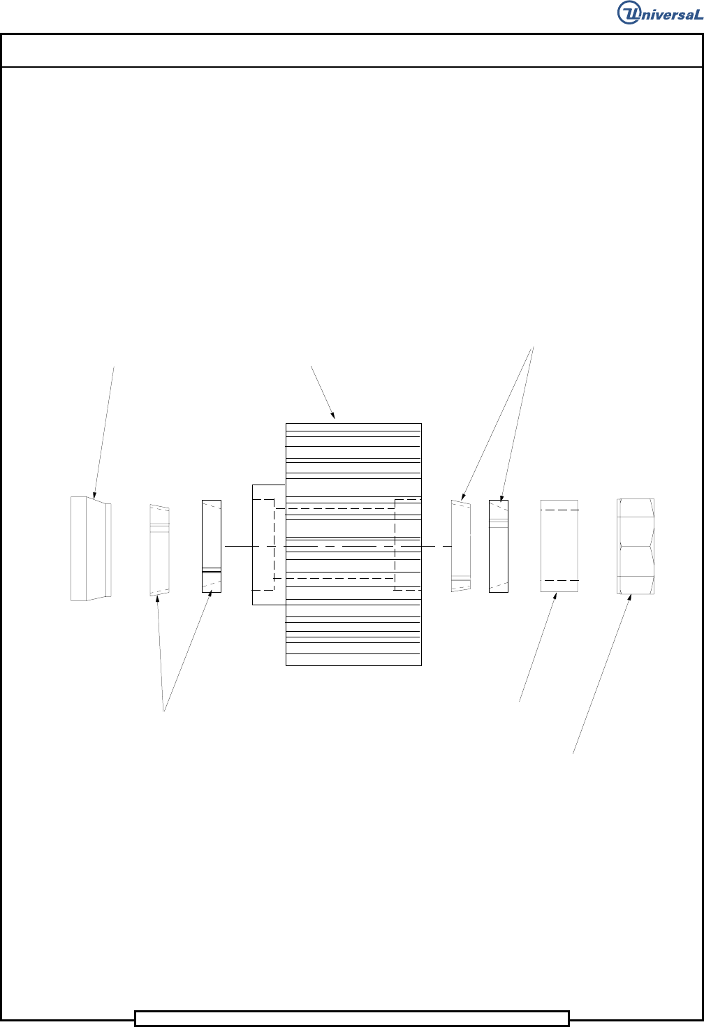
Page 12 T46230813 Rev . D DH P ositioning System Assembl y , P/T This Document Supports Assembly 46230813 Rev. D Vi e w - M (Typi cal 2 Places ) Spac er Loc kin g Elem ent Loc ki ng El ement Hex J am Nu t Spacer P u lle …

Page 13
DH Positioning System Assembly, P/T T46230813 Rev. D
This Document Supports Assembly 46230813 Rev. D
Notes
1
Torque to 90 IN-LBS.
2
Apply UIC # BLKM07389(Loctite 222), bottom plunger,then loosen 1/4 turn.
3
Apply UIC # BLKM07389(Loctite 222).
4
Torque screws to 20 FT-Lbs.
5
Remove stop block and dowel pins when widths exceed 10.25 IN.
6
Used only with board widths up to 10.25 IN. Any board widths larger,remove quides and use
Det.62 as a board quide. Remove Det. 140 and replace with screws located on bad board hopper
bracket. When not using board guides, attach to bad board hopper bracket.
7
Lubricate ball bushing and shafts with 10W oil after assembly. Refer to X-Y Rotary Positioning
Assembly ball screw lubrication procedure.
8
Lable fittings and tubing with corresponding line numbers.
9
Torque screws to 30 IN-Lbs.
10
Remove existing set screws and replace with hardware indicted.
11
Apply UIC # BLKM07402 (LOCTITE 242).
12
Fasten with Loctite 495.
13
Apply UIC # BLKM07402(Loctite 242) to threads of ball screw units and torque nut to 15 FT-LBS.
14
Secure using the tapped hole that lies completely on pad.
15
Set-up dimension from the face of the bearing bracket to the face of the pulley hub.
16
Locate the pulley on the shaft with the set screw, then tighten the two # 8 socket head cap
screws to secure the pulley to the shaft.
17
Orient the extended hub of bearing to the right,when viewing the shaft from front of machine.
18
Do not wrap cable around encoder body.
19
Electrostatic discharge precautions must be used during assembly.
20
Completely wipe off rust preventative and apply Bluegrease(BLKM07680) thoroughly to ball screw
units .
21
Apply Magnalube (40833809) to top of plunger.
22
Dowel pins to protrude from encoder plate 0.12 inches toward motor mounting casting.
23
Keep ESD covers on connectors until cable connectors are attached.