46230813.pdf - 第46页
Page 44 T46230813 Rev . D DH P ositioning System Assembl y , P/T This Document Supports Assembly 46230813 Rev. D Re ar Bo ar d Guide Dowe l Pin Shaf t Spac er St op Re ar Bo ar d Supp or t Re ar Su pp o rt Block Rot ary …
Page 43
DH Positioning System Assembly, P/T T46230813 Rev. D
This Document Supports Assembly 46230813 Rev. D
11. Remove the four 6 - 32 x 1/4 cap screws that secure the rear board
support/guide assembly to the rear support blocks and remove the rear
support blocks.
12. Remove the seven 6 - 32 x 3/16 button head screws that connect the
rear board guide to the rear board support.
13. If necessary, remove the two 10 - 32 x 3/8 cap screws that secure the
blocks to the rotary table and remove the blocks.
14. If necessary, remove the three 1/4 - 20 x 1/2 and one 1/4 - 20 x 1/4 cap
screws and dowel pins securing the four stops to the rotary table and
remove the stops.
15. Inspect all parts for wear or damage and replace as necessary.
16. Press seven 3/4 inch long and one 3/8 inch long dowel pins into the
rotary table. The 3/8 dowel pin must be installed in the front left stop
position shown.
17. Install the three stops to the rotary table using the 1/4 - 20 x 1/2 cap
screws and shaft spacers. Install the fourth stop to the rotary table
using the 1/4 - 20 x 1/4 low head cap screw in the front left stop
position shown.
18. Press the two blocks into the rotary table in the position shown. Using
a straight edge, square the blocks and secure to the rotary table using
the two 10 - 32 x 3/8 cap screws.
19. Assemble the rear board support and the rear board guide using the
seven 6 - 32 x 3/16 button head screws.
NOTE
When assembling the rear board support and the rear board guide,
determine the edge clearance required for your specific system
configuration. Move the board support fully forward for a 5mm edge
clearance or fully rearward for a 3mm edge clearance.
20. Assemble the rear board support/guide assembly to the two rear
support blocks using the four 6 - 32 x 1/4 cap screws.
21. Install the rear board support/guide assembly to the rotary table using
the two 8 - 32 x 5/8 cap screws and two tee nuts.
NOTE
Position the rear board support/guide assembly out of the way for the
remainder of this assembly procedure. It will be located as required
when the preproduction set up procedures are performed.
22. Assemble the front board support and the front board guide using the
seven 6 - 32 x 3/16 button head screws.
Page 44
T46230813 Rev. D DH Positioning System Assembly, P/T
This Document Supports Assembly 46230813 Rev. D
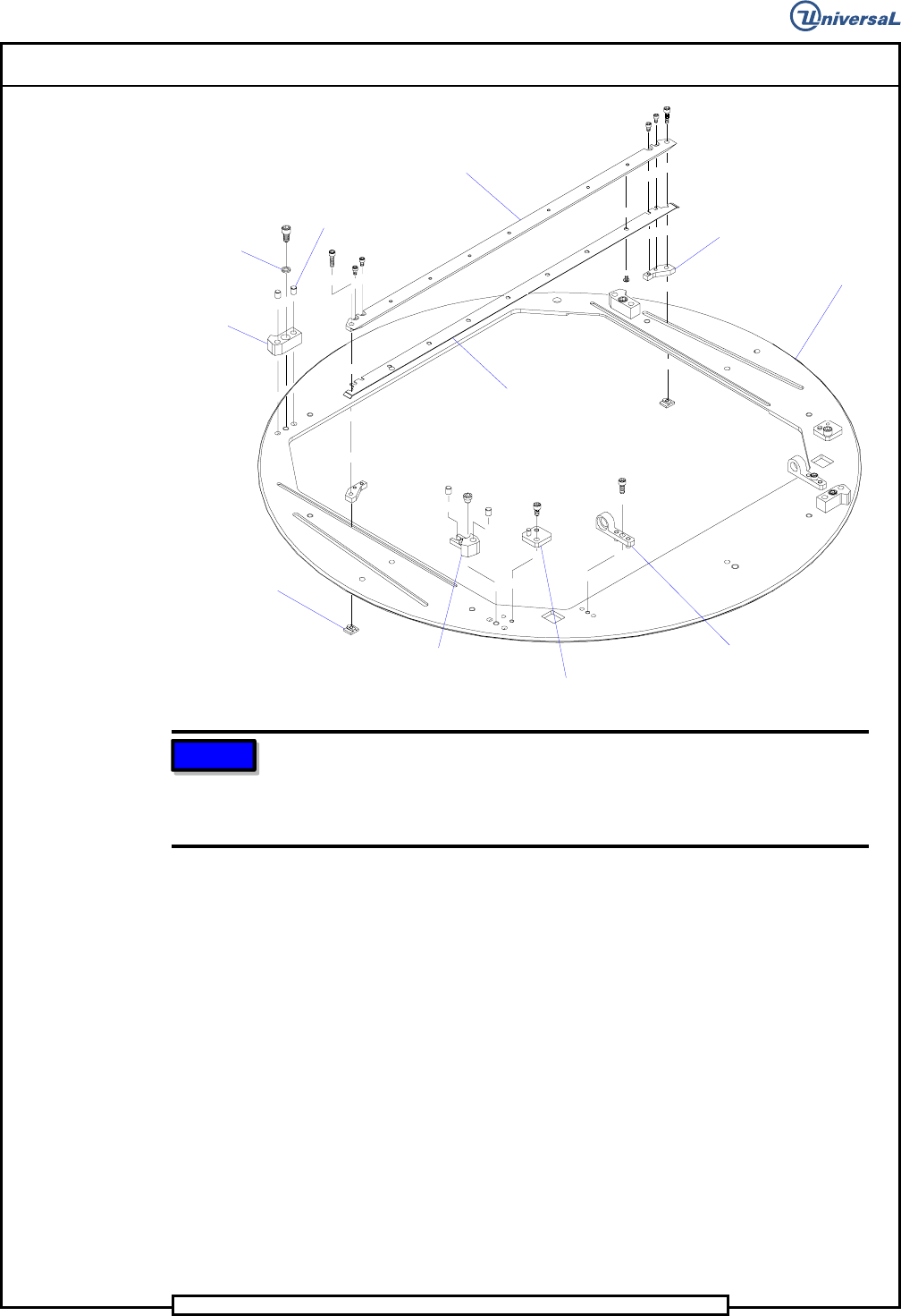
Rear Board
Guide
Dowel Pin
Shaft Spacer
Stop
Rear Board
Support
Rear Support
Block
Rotary
Table
Bearing
Block
Block
Stop
Tee Nut
NOTE
When assembling the rear board support and the rear board guide,
determine the edge clearance required for your specific system
configuration. Move the board support fully forward for a 5mm edge
clearance or fully rearward for a 3mm edge clearance.
23. Install the front board support/guide to the rotary table assembly in the
position shown using the two 10 - 32 x 1/4 button head screws.
24. Assemble the tooling plate to the shaft in the position shown using the
five 6 - 32 x 3/8 cap screws.
25. Slide the two torsion springs onto the shaft noting the orientation of
the springs. Rotate the spring to apply tension and ensure that the
springs engage the cutout on the tooling plate.
26. Assemble the bearings into the bearing blocks and slide them onto the
shaft in the position shown.
27. Assemble retaining ring to the right end of the shaft.
Page 45
DH Positioning System Assembly, P/T T46230813 Rev. D
This Document Supports Assembly 46230813 Rev. D
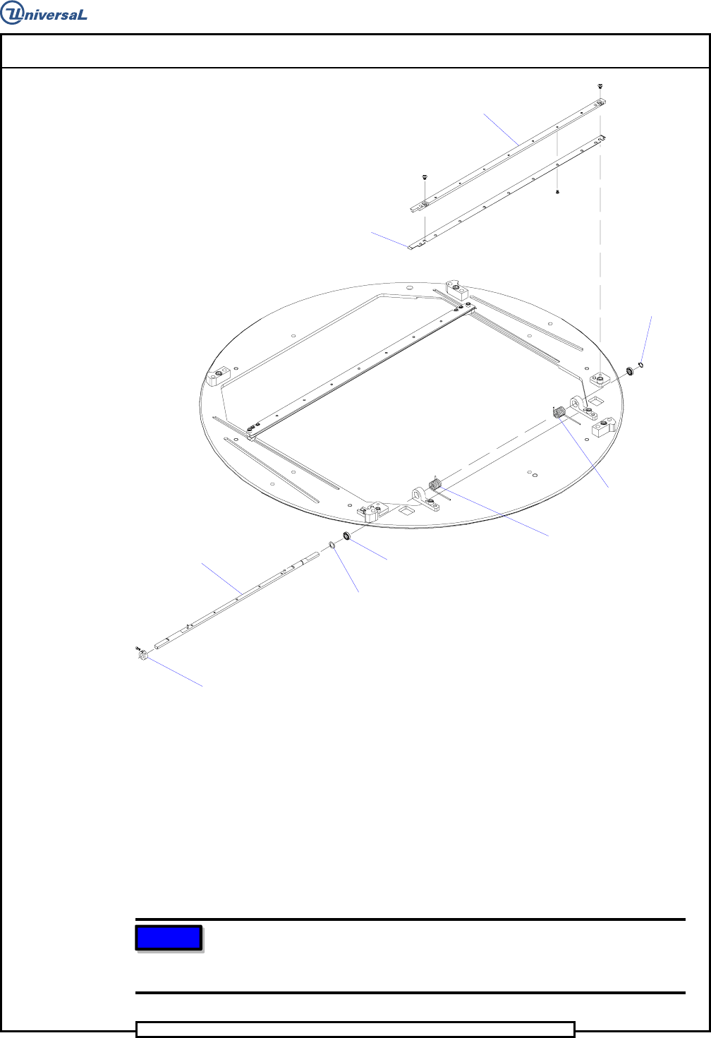
Front Board
Guide
Front Board
Support
Retaining
Ring
Torsion
Spring L
Torsion
Spring R
Radial
Bearing
Shaft
Spacer
Shaft
Collar
Clamp
28. Install the shaft assembly to the rotary table ensuring the torsion
springs properly engage the rotary table as shown. Secure the left
bearing block to the rotary table using the two 10 - 32 x 7/8 cap
screws. Align the right bearing block squarely to the rotary table then
secure it in place using the two 10 - 32 x 7/8 cap screws.
29. Assemble the collar clamp and shaft spacer to the left end of the shaft
so the retaining ring and shaft spacer are located firmly against their
respective bearing blocks. There should be no lateral movement of the
shaft.
NOTE
Squaring the bearing blocks to the rotary table provides a coarse
adjustment that will be finely adjusted at the board handling final set up
procedure.