46230813.pdf - 第48页
Page 46 T46230813 Rev . D DH P ositioning System Assembl y , P/T This Document Supports Assembly 46230813 Rev. D 30. Install the two tooling pin housings to the tooling plate using the four 6-32 x 3/8 button head screws.…
Page 45
DH Positioning System Assembly, P/T T46230813 Rev. D
This Document Supports Assembly 46230813 Rev. D
Front Board
Guide
Front Board
Support
Retaining
Ring
Torsion
Spring L
Torsion
Spring R
Radial
Bearing
Shaft
Spacer
Shaft
Collar
Clamp
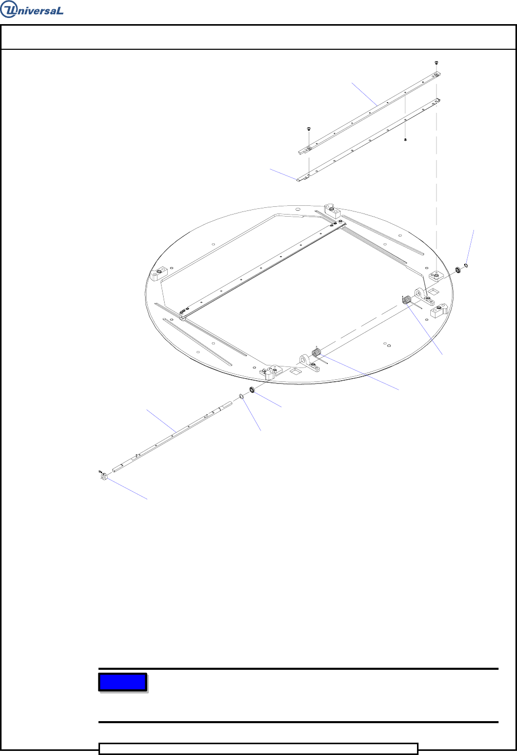
28. Install the shaft assembly to the rotary table ensuring the torsion
springs properly engage the rotary table as shown. Secure the left
bearing block to the rotary table using the two 10 - 32 x 7/8 cap
screws. Align the right bearing block squarely to the rotary table then
secure it in place using the two 10 - 32 x 7/8 cap screws.
29. Assemble the collar clamp and shaft spacer to the left end of the shaft
so the retaining ring and shaft spacer are located firmly against their
respective bearing blocks. There should be no lateral movement of the
shaft.
NOTE
Squaring the bearing blocks to the rotary table provides a coarse
adjustment that will be finely adjusted at the board handling final set up
procedure.
Page 46
T46230813 Rev. D DH Positioning System Assembly, P/T
This Document Supports Assembly 46230813 Rev. D
30. Install the two tooling pin housings to the tooling plate using the four
6-32 x 3/8 button head screws.
NOTE
Location of the tooling pin housings on the tooling plate will be determined
at the final set up procedure.
31. Attach the two tooling pins to the two tooling arms using the two 5- 40
x 1/4 cap screws.
Tooling Pin
Housing
Dowel Pin
Tooling Pin
Tooling
Pin Arm
Dowel Pin
Tooling Plate
32. Install the two tooling pin arm assemblies to the tooling housings
using the two 6 - 32 x 3/16 button head screws and washers.
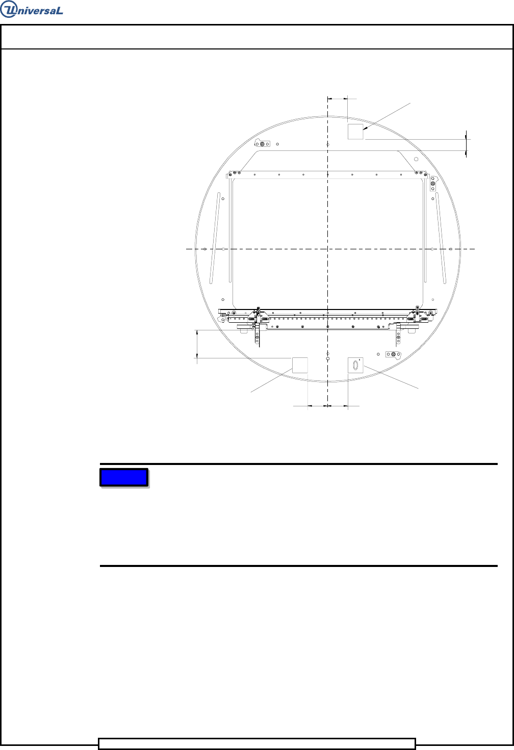
33. If necessary, install the two safety labels and the front label to the
rotary table at the positions shown.
Page 47
DH Positioning System Assembly, P/T T46230813 Rev. D
This Document Supports Assembly 46230813 Rev. D
2 x 2.750
1.250
2.000
2.000
2.000
Safety Label
Safety Label
Front Label
NOTE
Two different size tooling pins are supplied with the board handling
system. The standard tooling pin, UIC # 45810401, is supplied
assembled to the locators. The standard tooling pin is used for datum
holes .110 inch (2,8mm) to .187 inch (4,75mm) in diameter. The large
tooling pin, UIC # 45810402, is supplied in a bag attached to the
workboard holder. The large tooling pin is used for datum holes .188 inch
(4,76mm) to .250 inch (6,35mm) in diameter.
Actuator Assembly Disassembly/Assembly
1. Remove two 10 - 32 x 5/8 cap screws securing the front board guide to
the plate and remove the front board guide.
2. Remove two shoulder screws that secure the left switch assembly to the
plate and remove the left switch assembly. Perform the same for the
right switch assembly.