46230813.pdf - 第22页
Page 20 T46230813 Rev . D DH P ositioning System Assembl y , P/T This Document Supports Assembly 46230813 Rev. D 163 80010403 SD P 7/16 X 1 1/2 2 EA 164 80000607 SH CS 1/4-20 X 1 2 EA 166 BLKE01071 CLAMP, 3/16 2 EA 167 8…
Page 19
DH Positioning System Assembly, P/T T46230813 Rev. D
This Document Supports Assembly 46230813 Rev. D
131 18164000 WHEEL,GUIDE 4 EA
132 47540603 STUD,GUIDE WHEEL 4 EA
133 17597001 Y FRAME 1 EA
134 14339000 SHAFT,X AXIS 2 EA
135 80000519 SHCS 10-32 X 1 19 EA
136 80004704 SOC SET SCR,FL.PT 6-32 X 3/8 4 EA
137 20189000 ACTUATOR 2 EA
138 48240001 SPACER 2 EA
139 15118000 BUSHING 3 EA
140 80000517 SHCS 10-32 X 3/4 3 EA
141 80000302 SHCS 6-32 X 3/8 18 EA
142 45292801 RAIL,ACTUATOR BRKT 1 EA
143 80002403 SFHS 6-32 X 1/2 3 EA
144 80000609 SHCS 1/4-20 X 1 1/2 1 EA
145 48226801 PLATE,ENCODER 1 EA
146 14330002 RETAINER, BEARING 1 EA
147 80001501 SBHS 8-32 X 1/4 4 EA
148 14340000 SUPPORT,BRG 1 EA
149 80000608 SHCS 1/4-20 X 1 1/4 3 EA
150 17802000 PLATE,MTG 1 EA
151 17595002 COVER 1 EA
152 48216301 MOTOR,BRUSHLESS,DC,ENCODER 2 EA
153 48236102 RETAINER,BELLOW 2 EA
154 80015104 HEX JAM NUT 5/16-24 2 EA
155 44973301 BRACKET,SENSOR 2 EA
156 44460003 PROXIMITY SWITCH 2 EA
157 80002503 SFHS 8-32 X 5/8 6 EA
158 80010104 DOWEL, 1/4 X 7/8 4 EA
159 15179000 CLAMP, ENCODER 1 EA
160 48237501 BEARING,BALL,DOUBLE ROW 2 EA
161 10249101 SPRING 4 EA
162 80010407 SDP 7/16 X 1/2 4 EA
Page 20
T46230813 Rev. D DH Positioning System Assembly, P/T
This Document Supports Assembly 46230813 Rev. D
163 80010403 SDP 7/16 X 1 1/2 2 EA
164 80000607 SHCS 1/4-20 X 1 2 EA
166 BLKE01071 CLAMP, 3/16 2 EA
167 80018807 FW 1/4 2 EA
168 48213801 PULLEY,MOTOR 2 EA
169 10457013 CLAMP,COLLAR 2 EA
170 48239901 SPACER 2 EA
171 18332000 SCREW, THUMB 2 EA
172 48236201 RETAINER,BEARING 2 EA
173 48395101 CABLE ASSY,LIMIT WIRE 1 EA
174 30648505 BRACKET, SUPPORT 1 EA
Page 21
DH Positioning System Assembly, P/T T46230813 Rev. D
This Document Supports Assembly 46230813 Rev. D
Functional Description
The dual X-Y positioning system contains the X and Y positioning tables
which are actuated by the servo drive motors. When the motors receive a
signal they move the positioning system to predetermined coordinates
contained in the pattern program. Rotary encoders monitor the positioning
system location to ensure the positional accuracy. The X and Y tables mount
on the base and position the dual rotary tables.
Maintenance Concept
The following table defines the recommended Maintenance Concept for this
assembly. For a more detailed explanation of the Maintenance Concept and
its structure refer to the Prerequisite Information/Introduction module and
the periodic preventive maintenance as presented later in this document.
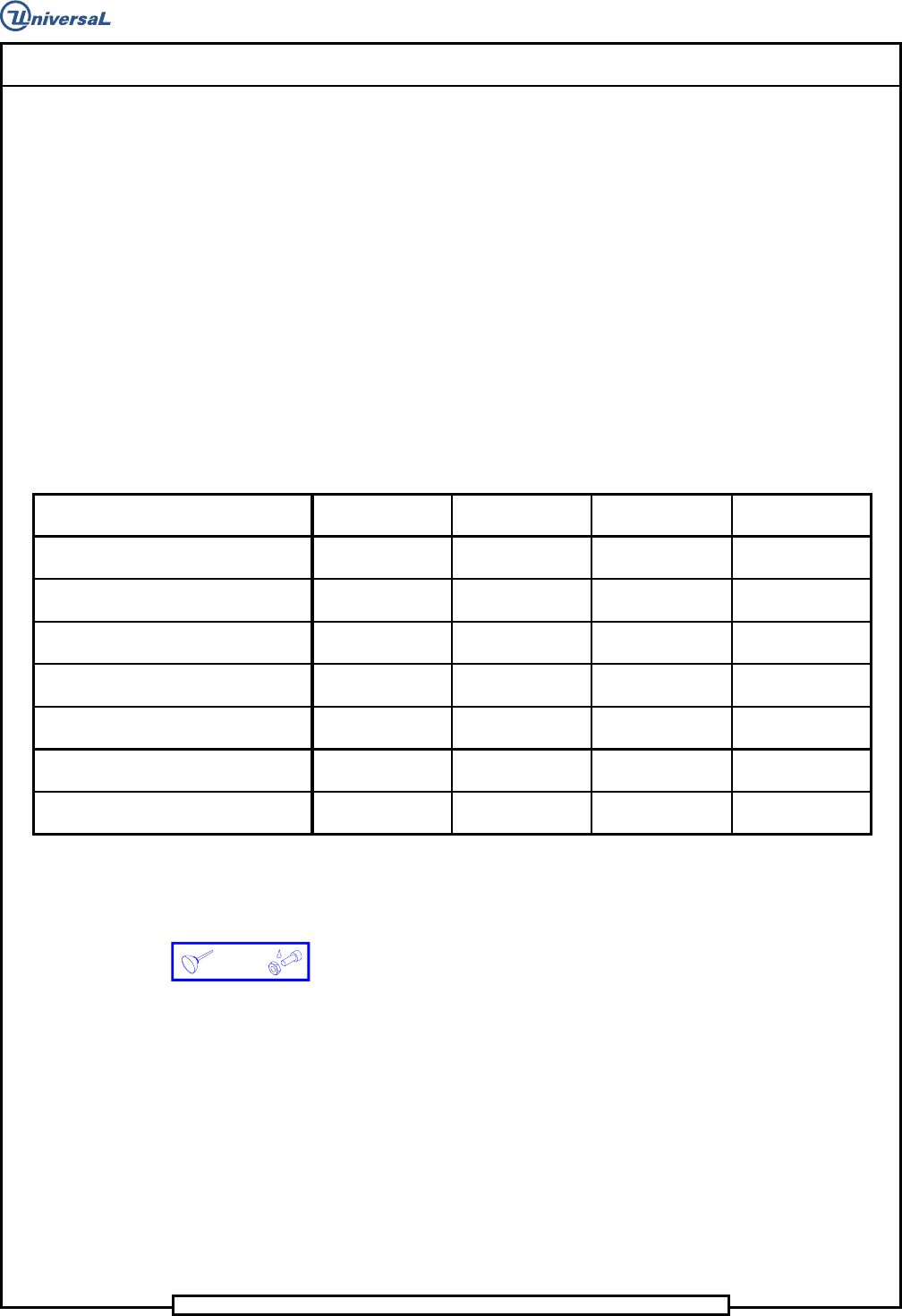
Maintenance Procedures
Recommended
Frequency
Minimum Skill
Required
Spares Kit
Required
Tool Kit Required
Check Rotary Table squareness Weekly
Maintenance
Technician
No Yes
Check Rotary Table air motor drive wheel Weekly
Maintenance
Technician
No No
Lubricate the Rotary Table lock assembly Weekly
Maintenance
Technician
No No
Flush and Lubricate the X-Y ball bushings Monthly
Maintenance
Technician
No No
Clean and lubricate linear shafts Monthly
Maintenance
Technician
No No
Lubricate X-Y ball screws Monthly
Maintenance
Technician
No No
Diassemble, clean and lubricate Rotary
Table lock assy
Semiannually
Maintenance
Technician
No Yes
Prerequisite Information
• See the Prerequisite Information/Introduction document for Adhesive
and Lubricant icon information and definitions.