46230813.pdf - 第49页
Page 47 DH P ositioning System Assembl y , P/T T46230813 Rev . D This Document Supports Assembly 46230813 Rev. D 2 x 2.75 0 1. 25 0 2. 00 0 2.000 2. 00 0 Safety Label Safety Label Front Label NOTE Two different size tool…
Page 46
T46230813 Rev. D DH Positioning System Assembly, P/T
This Document Supports Assembly 46230813 Rev. D
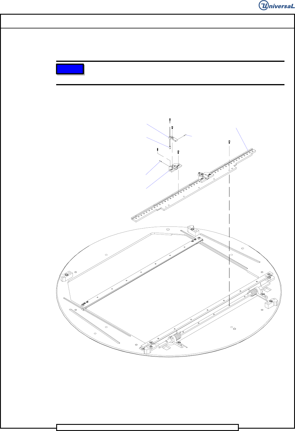
30. Install the two tooling pin housings to the tooling plate using the four
6-32 x 3/8 button head screws.
NOTE
Location of the tooling pin housings on the tooling plate will be determined
at the final set up procedure.
31. Attach the two tooling pins to the two tooling arms using the two 5- 40
x 1/4 cap screws.
Tooling Pin
Housing
Dowel Pin
Tooling Pin
Tooling
Pin Arm
Dowel Pin
Tooling Plate
32. Install the two tooling pin arm assemblies to the tooling housings
using the two 6 - 32 x 3/16 button head screws and washers.
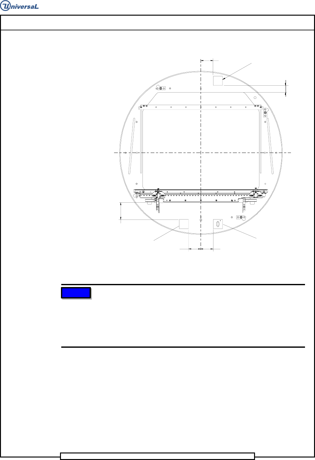
33. If necessary, install the two safety labels and the front label to the
rotary table at the positions shown.
Page 47
DH Positioning System Assembly, P/T T46230813 Rev. D
This Document Supports Assembly 46230813 Rev. D
2 x 2.750
1.250
2.000
2.000
2.000
Safety Label
Safety Label
Front Label
NOTE
Two different size tooling pins are supplied with the board handling
system. The standard tooling pin, UIC # 45810401, is supplied
assembled to the locators. The standard tooling pin is used for datum
holes .110 inch (2,8mm) to .187 inch (4,75mm) in diameter. The large
tooling pin, UIC # 45810402, is supplied in a bag attached to the
workboard holder. The large tooling pin is used for datum holes .188 inch
(4,76mm) to .250 inch (6,35mm) in diameter.
Actuator Assembly Disassembly/Assembly
1. Remove two 10 - 32 x 5/8 cap screws securing the front board guide to
the plate and remove the front board guide.
2. Remove two shoulder screws that secure the left switch assembly to the
plate and remove the left switch assembly. Perform the same for the
right switch assembly.

Page 48
T46230813 Rev. D DH Positioning System Assembly, P/T
This Document Supports Assembly 46230813 Rev. D
3. If necessary, remove the shoulder screws, compression springs and 10 -
32 x 3/4 set screw from each switch bracket.
4. On the left switch assembly remove the two 8 - 32 x 7/8 flat head
screws that secure the strap and sensor switch to the left switch bracket
and remove the strap and switch. Perform the same for the right switch
assembly.
5. Remove the two 6 - 32 x 3/4 cap screws that secure the strap to the air
cylinders and remove the strap.
6. Remove the two 10 - 32 x 5/8 cap screws that secure the left air
cylinder assembly to the plate and remove the left air cylinder
assembly. Perform the same for the right air cylinder assembly.
7. Remove the 10 - 24 x 5/8 cap screw that secures the actuator to the left
air cylinder and remove the actuator. Perform the same for the right air
cylinder assembly.
8. Remove the two 10 - 24 x 1/2 cap screws that secure the cylinder
bracket to the left air cylinder and remove the bracket. Perform the
same for the right air cylinder assembly.
9. If necessary, remove the three male elbows and the straight fittings
from the air cylinders.
10. Inspect all parts for wear or damage and replace as necessary.
11. Install the male elbow and straight fitting to the left air cylinder, as
shown, and label them 107 and 106 respectively. Install the two male
elbow fittings to the right air cylinder, as shown, and label them 107
and 106 respectively.
12. Install the cylinder bracket to the left air cylinder using the two 10 - 24
x 1/2 cap screws. Perform the same for the right cylinder and cylinder
bracket.
13. Loosely install the left actuator to the left air cylinder piston. Rotate
the actuator counter clockwise until the flats on the piston shaft
contact the grove on the actuator then tighten the cap screws. Perform
the same for the right actuator and right air cylinder.
14. Loosely install the left air cylinder assembly to the plate using the two
10 - 32 x 5/8 cap screws. Perform the same for the right air cylinder
assembly. Loosely install the strap to the air cylinder pistons using the
two 6 - 32 x 3/4 cap screws as shown and move the strap up and down
to self align the air cylinders. Tighten the two 6 - 32 x 3/4 cap screws
securing the strap to the air cylinder pistons and the four 10 - 32 x 5/8
cap screws securing the air cylinder assemblies to the plate.