JAKA Zu sp使用手册 -英文版.pdf - 第5页
JAKA Zu Sp 5 Chapter 2 Description JAKA Zu sp system contains APP, robot, control cabinet and F/T sensor equipment. As shown in figure 2, F/T sensor equipment includes six-dimensions torque sensor etc. As shown in figure…
4 JAKA Zu Sp
Chapter 1 Instruction
1.1 Background
Industrial robot arm has been widely used in various industrial scenes. It can be used for
industrial applications such as parts grasping, assembling, material handling, etc. However,
traditional industry robot cannot meet small and medium-sized enterprises requirements because
their products are usually small batch, customization and quickly renewed. JAKA Zu series of
collaborative robots can be deployed quickly and programmed easily which can help these
enterprises solve their problems effectively.
1.2 Purpose
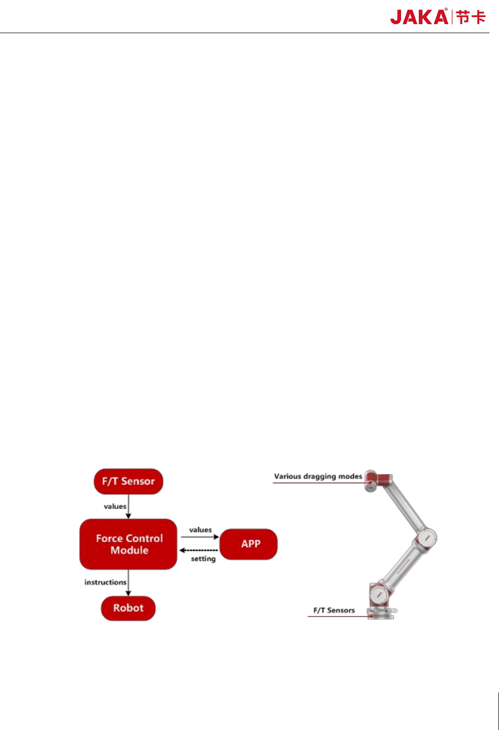
JAKA Zu sp is designed to use industrial-grade F/T sensors and integrated force control
algorithms to improve the perception of collaborative robot which can provide better
human-computer interaction experience and security guarantee for customers. As shown in figure 1,
the F/T sensor is installed on the base of the robot, and the force values are transmitted to the robot
controller in real time. When the robot body or end-effector is subjected to external forces, the force
control module will make the robot stop moving immediately, so as to ensure the safety of people
and machines. At the same time, the operator can lead the robot to move in three directions through
any part of the robot body.
.
Fig 1. JAKA Zu sp function diagram
JAKA Zu Sp 5
Chapter 2 Description
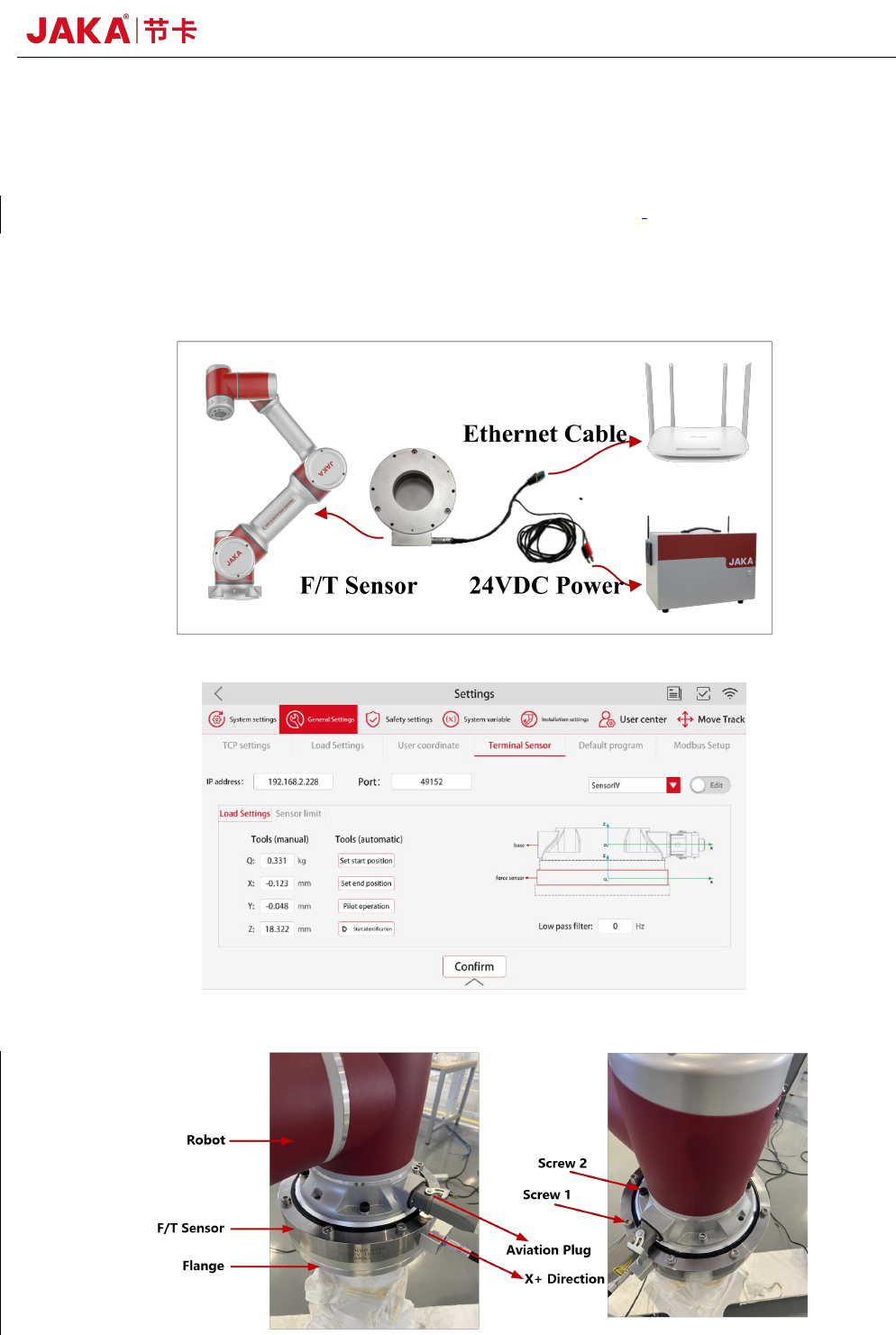
JAKA Zu sp system contains APP, robot, control cabinet and F/T sensor equipment. As shown
in figure 2, F/T sensor equipment includes six-dimensions torque sensor etc. As shown in figure 3,
operator can set communication parameters in APP. For convenience, the data acquisition card has
been integrated into F/T sensor.
Fig 2. JAKA Zu sp system diagram
Fig 3. Force control module communication setting
6 JAKA Zu Sp
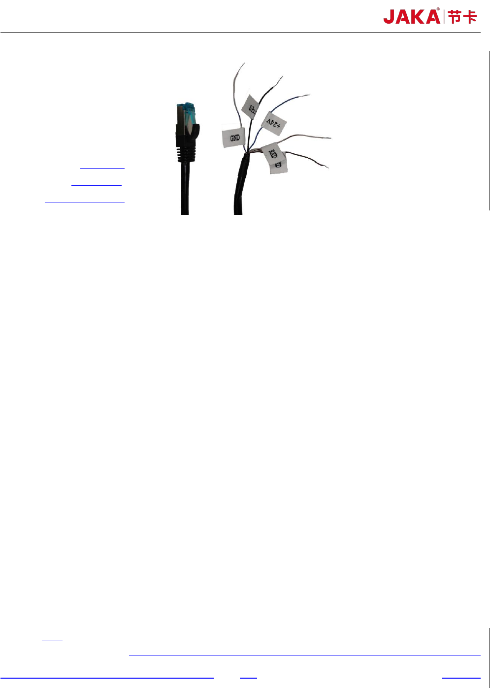
+24V
:
blue
Shield
:
black
GND:white and blue
Fig 4. Force control module communication setting
Chapter 3 JAKA Zu sp System setup
As shown in figure 2 and figure 3, it is easy to set up JAKA Zu sp system. The specific setup
process is as follows:
a. The aviation plug direction of the robot base shall be consistent with the X+ direction of the F/T
sensor. The screw length should not be too long to damage the F/T sensor. In order to ensure the
F/T sensor can be in uniform contact with the flange or the robot base, it’s necessary to tighten
the screws gradually in diagonal order. More details are shown as figure 4. The reference
tightening torque for screws is shown as table 1. 2-D drawings of flange and F/T sensor are
shown as figure 8 and figure 9.
b. The F/T sensor can be supplied by robot controller or the customer's additional 24V DC power.
In order to receive the F/T sensor signal correctly, it is necessary to ensure that the ground wire
and shielding wire are connected to the same negative electrode. It shall be ensured that the
controller and the F/T sensor are configured in the same network segment.
c. At present, the F/T sensor IP has been fixed to 192.168.2, so the router needs to be configured to
192.168.2 network segment to establish the communication. The port number is fixed to 4008.
Chapter 4 Use of JAKA Zu sp
a. Collision Detection
As shown in figure 5, after setting the 【IP address】 and 【Port】 number, 【Confirm】 and
tab 【Edit】to switch to the running mode. In the payload setting interface, set the mass and centroid
of the payload in 【Manual input mode】. When executing the program, payload can also be set in the
program instruction. In the interface of collision protection, set the sensitivity level of collision