JAKA Zu sp使用手册 -英文版.pdf - 第7页
JAKA Zu Sp 7 detection. The higher the level, the less sensitive the detection collision is. When executing the program, if the payload need to be changed, the collision should be closed in advance in ord er t o reset th…
6 JAKA Zu Sp
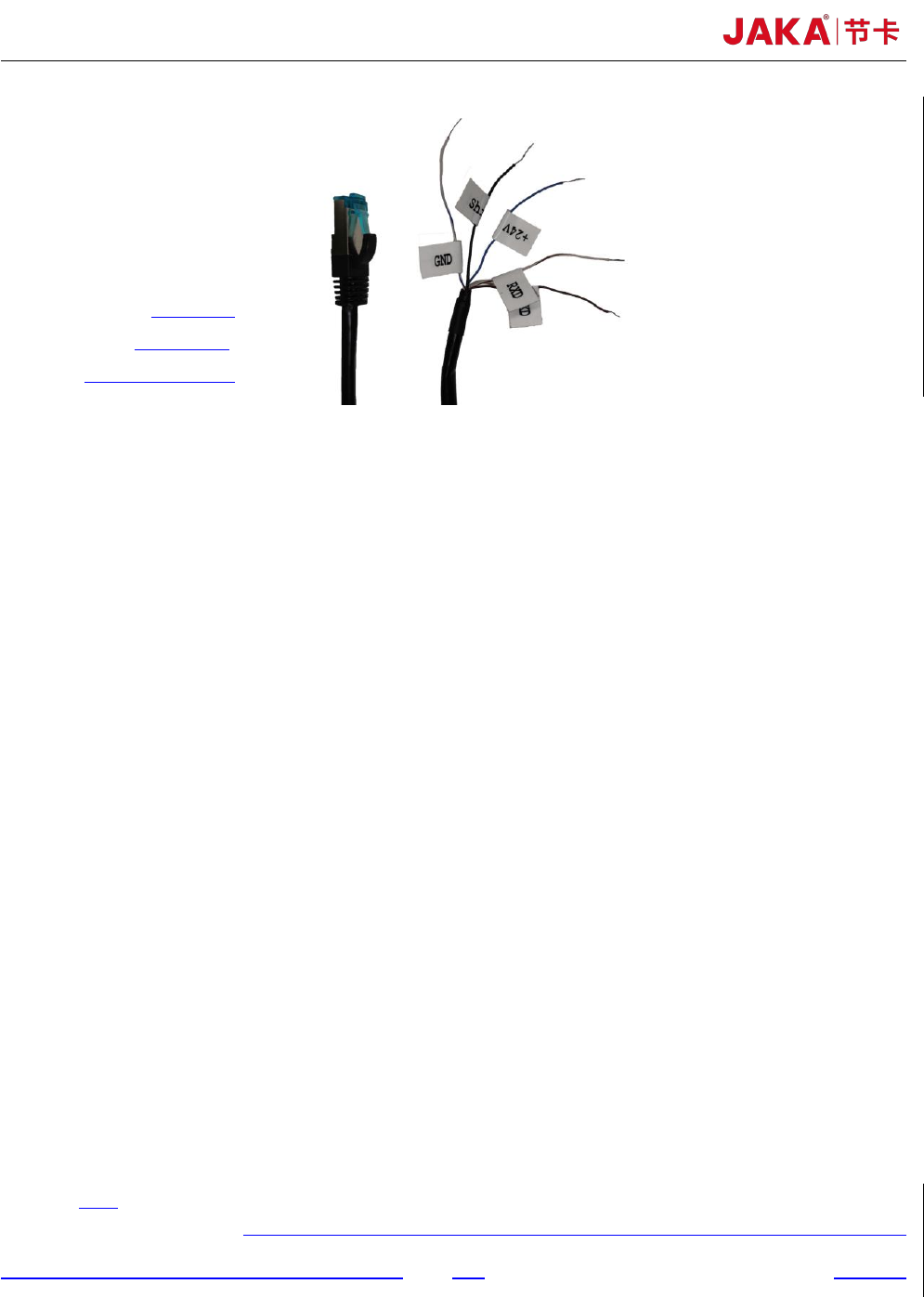
+24V
:
blue
Shield
:
black
GND:white and blue
Fig 4. Force control module communication setting
Chapter 3 JAKA Zu sp System setup
As shown in figure 2 and figure 3, it is easy to set up JAKA Zu sp system. The specific setup
process is as follows:
a. The aviation plug direction of the robot base shall be consistent with the X+ direction of the F/T
sensor. The screw length should not be too long to damage the F/T sensor. In order to ensure the
F/T sensor can be in uniform contact with the flange or the robot base, it’s necessary to tighten
the screws gradually in diagonal order. More details are shown as figure 4. The reference
tightening torque for screws is shown as table 1. 2-D drawings of flange and F/T sensor are
shown as figure 8 and figure 9.
b. The F/T sensor can be supplied by robot controller or the customer's additional 24V DC power.
In order to receive the F/T sensor signal correctly, it is necessary to ensure that the ground wire
and shielding wire are connected to the same negative electrode. It shall be ensured that the
controller and the F/T sensor are configured in the same network segment.
c. At present, the F/T sensor IP has been fixed to 192.168.2, so the router needs to be configured to
192.168.2 network segment to establish the communication. The port number is fixed to 4008.
Chapter 4 Use of JAKA Zu sp
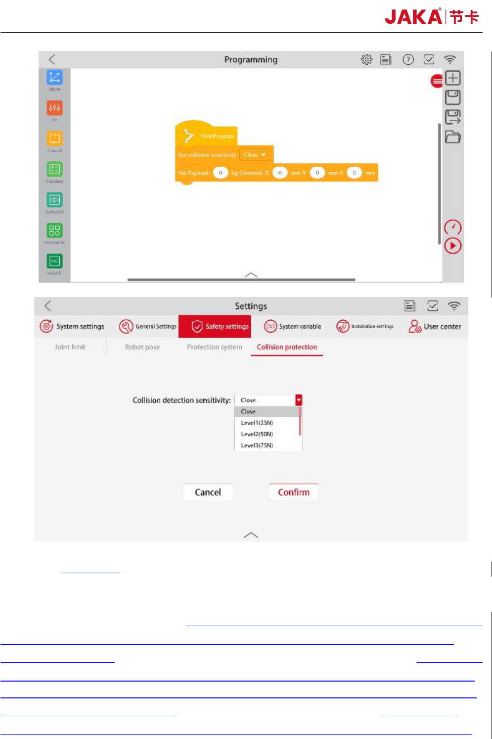
a. Collision Detection
As shown in figure 5, after setting the 【IP address】 and 【Port】 number, 【Confirm】 and
tab 【Edit】to switch to the running mode. In the payload setting interface, set the mass and centroid
of the payload in 【Manual input mode】. When executing the program, payload can also be set in the
program instruction. In the interface of collision protection, set the sensitivity level of collision
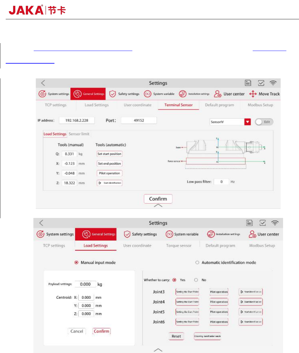
JAKA Zu Sp 7
detection. The higher the level, the less sensitive the detection collision is. When executing the
program, if the payload need to be changed, the collision should be closed in advance in order to
reset the payload.
8 JAKA Zu Sp
Fig 5. Collision detection function
b. Dragging and teaching mode
As shown in figure 5, after setting the communication IP, port number and payload,in the
Manual interface, click
【
Configure
】
to select the dragging axis. Click
【
Drag
】,
then operator can
lead the robot to move at a low speed. 【Damping force】 is the constant resistance when the robot
runs. The greater the dampling force is, the greater the force required to push the robot through
dragging and teaching.
【
Damping force
】
values are recommended greater than 40N.
【
springback
】
can make the robot return to the position initialized when the dragging and teaching mode is turned
on. The farther the robot is from the initialization position, the greater the force required to push the
robot through dragging and teaching.【springback】 values are usually set to 0 when using the
dragging and teaching mode. If the robot vibrates during the dragging and teaching process, please