JAKA Zu sp使用手册 -英文版.pdf - 第9页
JAKA Zu Sp 9 [exit] t he drag and teaching mode and i ncrease the am ount of damping force setti ng. Fig 6. Dragging function Chapter 5 Use Notic e a. If setting the payload incorrectly , the robot may enc ounter collisi…
8 JAKA Zu Sp
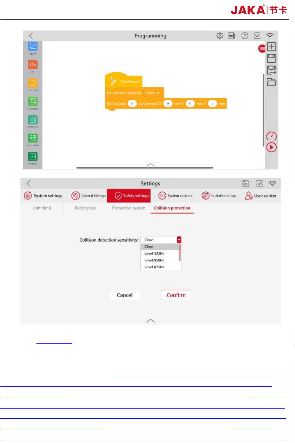
Fig 5. Collision detection function
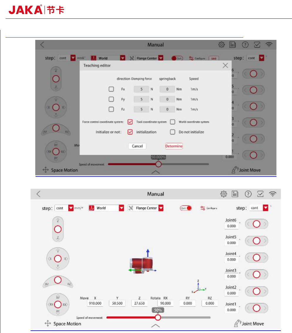
b. Dragging and teaching mode
As shown in figure 5, after setting the communication IP, port number and payload,in the
Manual interface, click
【
Configure
】
to select the dragging axis. Click
【
Drag
】,
then operator can
lead the robot to move at a low speed. 【Damping force】 is the constant resistance when the robot
runs. The greater the dampling force is, the greater the force required to push the robot through
dragging and teaching.
【
Damping force
】
values are recommended greater than 40N.
【
springback
】
can make the robot return to the position initialized when the dragging and teaching mode is turned
on. The farther the robot is from the initialization position, the greater the force required to push the
robot through dragging and teaching.【springback】 values are usually set to 0 when using the
dragging and teaching mode. If the robot vibrates during the dragging and teaching process, please
JAKA Zu Sp 9
[exit] the drag and teaching mode and increase the amount of damping force setting.
Fig 6. Dragging function
Chapter 5 Use Notice
a. If setting the payload incorrectly, the robot may encounter collision detection falsely.
Operator shall ensure that the payload setting is accurate or reduce collision sensitivity if conditions permit.
b. Make sure that the F/T sensor and robot controller are configured in the same network segment.
c. Make sure that the aviation plug direction of the robot base shall be consistent with the X+ direction of the
sensor. Coordinate system of the F/T sensor is shown in figure 10.
d. The F/T sensor’s IP is not recommended modified. If needed, please feel free to contact our technical
support.
10 JAKA Zu Sp
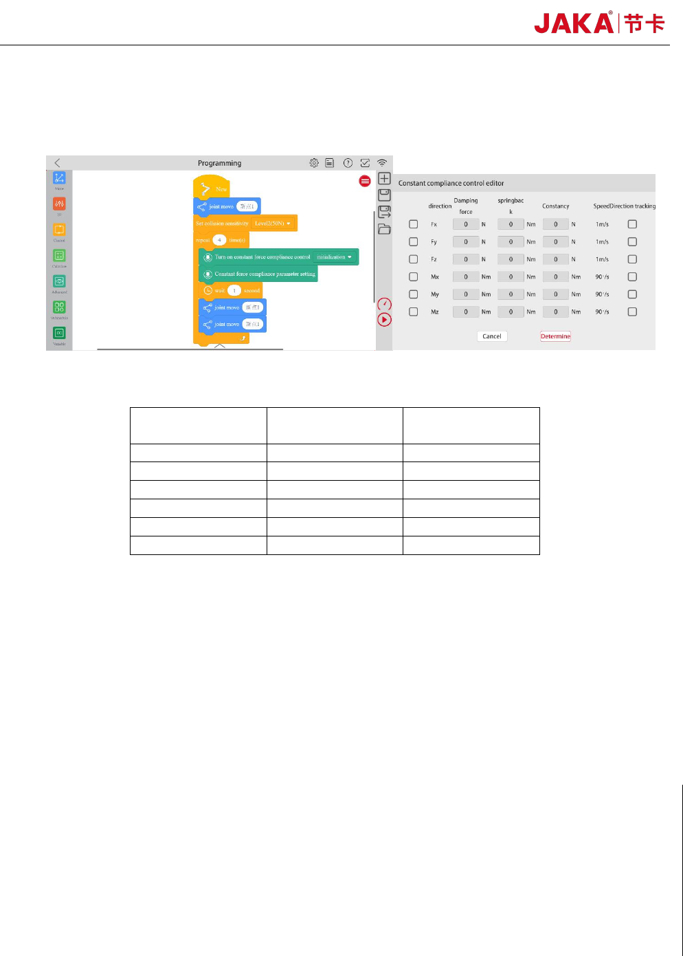
e. F/T sensor initialization is recommended at intervals. As figure 7 shown, three program instructions are
needed. 【Turn on constant force compliance control】 initialization, all parameters are set 0 and no boxes
are checked in 【Constant force compliance parameter setting】,【wait】 1 second.
Fig 7. F/T sensor initialization
Table 1. The reference tightening torque for screws
Metric System
British System
Reference
values(Nm)
M3
#6
2.00
M4
#8
4.00
M5
#10
8.00
M6
1/4’’
13.00
M8
5/16’’
35.00
M10
3/8’’
45.00