YG100R_Ope_E.pdf - 第36页
1-8 1 Part names and functions 3 . 2 N o z z l e t y p e s T o e n s u r e s t a b l e c o m p o n e n t p i c k u p , t h e c o r r e c t n o z z l e t h a t m a t c h e s t h e c o m p o n e n t m u s t b e u s e d . T…
1-7
1
Part names and functions
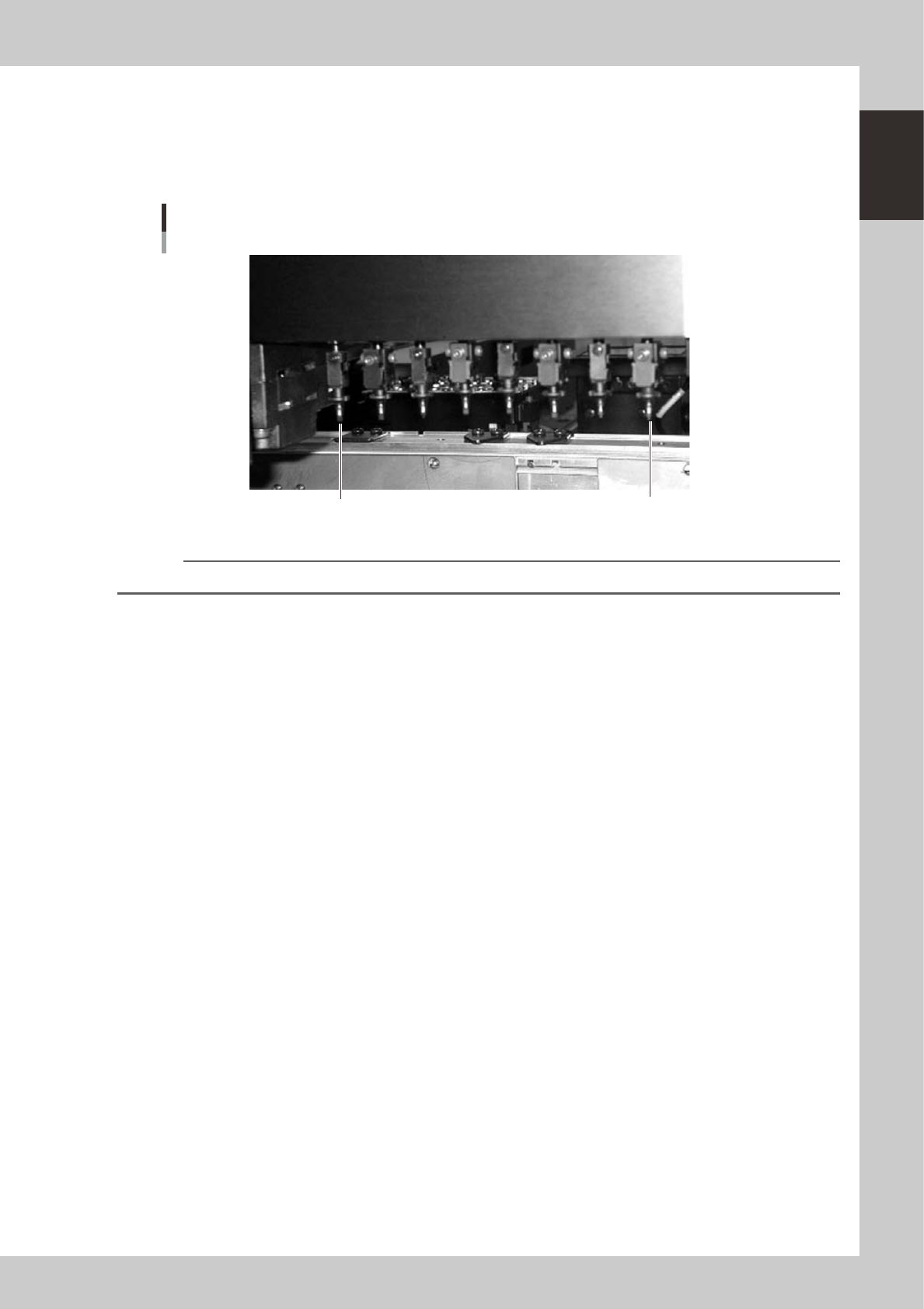
3.1.2 Eight-in-line multi-head (standard) assembly
As with the FNC type head assembly, this standard type eight-in-line multi-head assembly has 8 heads arranged
in a row for component pickup and placement. Head numbers are designated from 1 to 8, from the right as
viewed from the front of the head assembly. The spacing of adjacent nozzles attached to the head assembly is
16mm, which is identical to the pitch of the feeder installation holes in the feeder plates.
Eight-in-line multi-head assembly
Standard type
Head 8
Head 1
23106-M1-00
n
NOTE
Heads 1, 3, 5 and 7 use a roller-lock clamp mechanism for holding a nozzle more securely.
1-8
1
Part names and functions
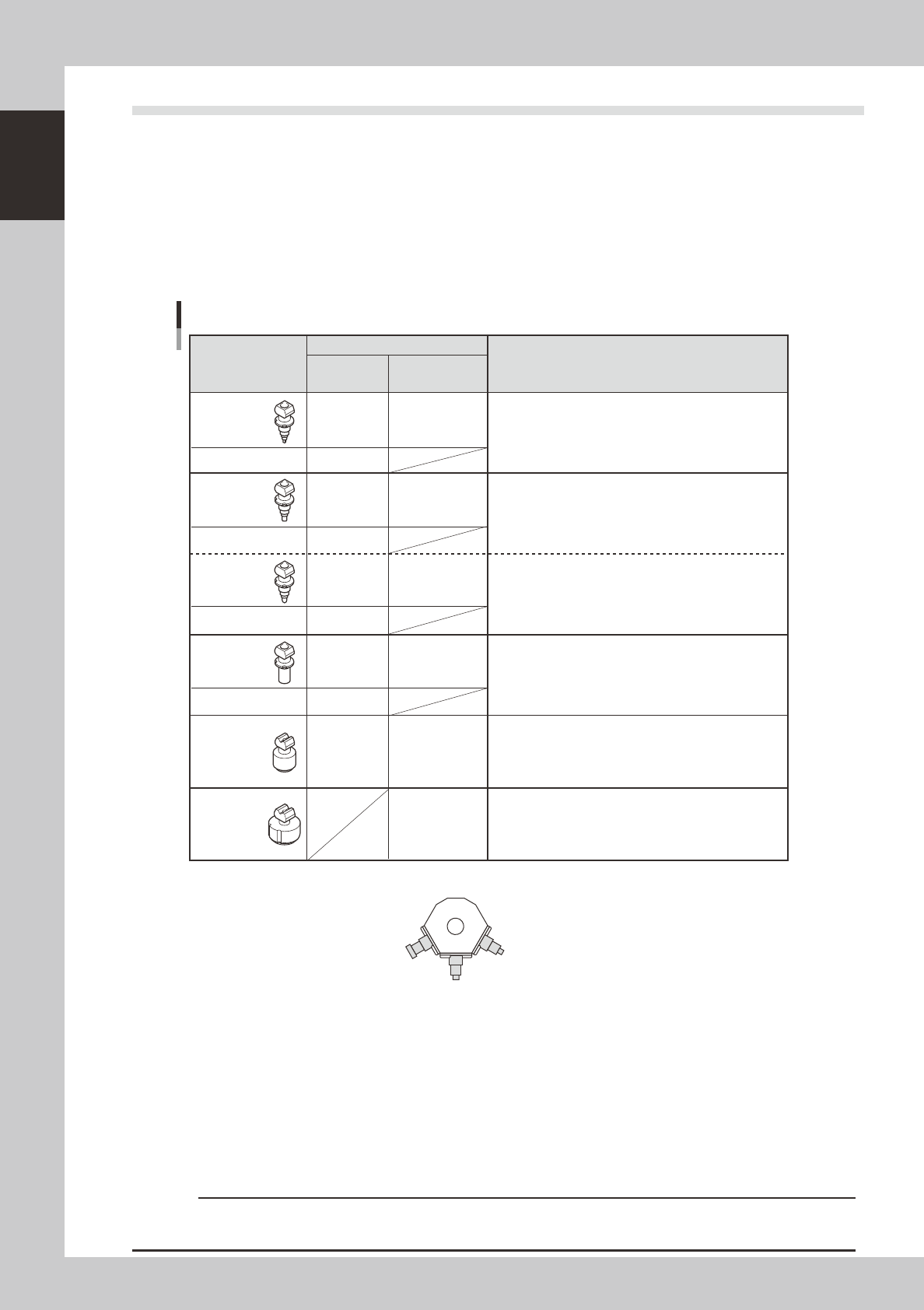
3.2 Nozzle types
To ensure stable component pickup, the correct nozzle that matches the component must be used. The
following sections explain typical nozzles which can be attached to each head.
3.2.1 Nozzles for the eight-in-line head assemblies
On the eight-in-line multi-head (FNC) assembly, five types of standard nozzles (Type A) can be chosen and
attached to Heads 1, 3, 5 or 7 while FNC nozzles (Type F) can be attached to Heads 2, 4, 6 and 8.
On the eight-in-line multi-head (standard) assembly, six types of nozzles (Type A) can be chosen and attached
to the mating heads (manual nozzle change).
Type 211A
Type 211F
Type 212A
Type 212F
(Type 219A)
(Type 219F)
Type 213A
Type 213F
Type 214A
Type 215A
FNC type Standard type
1, 3, 5, 7
2, 4, 6, 8
1, 3, 5, 7
2, 4, 6, 8
1, 3, 5, 7
2, 4, 6, 8
1, 3, 5, 7
2, 4, 6, 8
1, 3, 5, 7
All heads
All heads
All heads
All heads
All heads
1, 3, 5, 7
Eight-in-line multi-head nozzles
Type 212 F
Type 213F Type 211F
2
1
3
4532 to 7343 size components, 10 mm SOP,
5s5mm to 16s16mm QFP, etc.
20 to 30mm SOP, 10s10mm to 30s30mm QFP and BGA, etc.
16s16mm to 54s54mm connectors, 20s20mm to 54s54mm QFP
and BGA, etc.
Nozzle Type
Head No.
Typical Components
0603 to 1005 size chip components, mini-mold transistors, etc.
1608 to 3216 size chip components, mini-mold transistors, etc.
1608 to 3216 size chip components, mini-mold transistors, etc.
1 to 3: Index holder No.
* Type 212 and Type 219 nozzles cannot be selected at the same time. Only one of them can be selected for use. This
means that Type 212A and 212F nozzles can only be used when Type 212 is selected.
23107-M1-00
Type A nozzles
Type A nozzles (211A, 212 (219)A, 213A, and 214A) can be attached to all heads of eight-in-line standard multi-head
assemblies or to Heads 1, 3, 5 and 7 of eight-in-line FNC multi-head assemblies.
Type 215A nozzle can only be attached to eight-in-line standard multi-head assemblies.
Type F nozzles
The eight-in-line FNC multi-head assemblies have a flying nozzle changer (FNC) at the tip of Heads 2, 4, 6 and 8. Three
types of nozzles (Types 211F, 212F or 219F, and 213F) can be attached to each FNC head.
c
CAUTION
The above nozzles are specifically designed for use with the YG100R surface mounters. Do not use them for other
machines.
1-9
1
Part names and functions
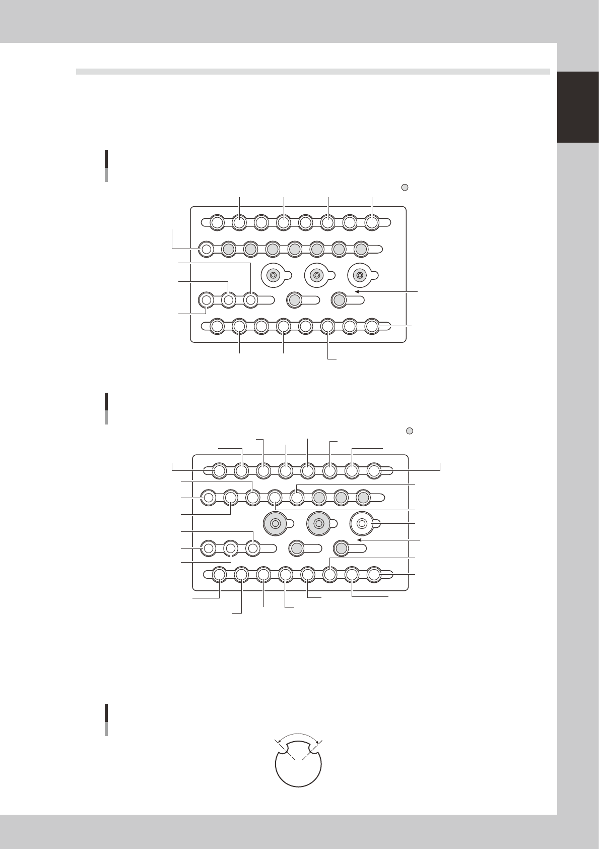
3.3 Nozzle station (option)
The nozzle station accommodates various nozzles for automatic change.
The YG100RA with an optional nozzle station enables automatic nozzle change on Heads 1, 3, 5 and 7 (not
on Heads 2, 4, 6 and 8). The YG100RB with an optional nozzle station enables automatic nozzle change on all
heads.
The drawings below show the nozzle station No. and the allotted head No. and mating nozzle type.
YG100R nozzle station
For FNC type
13141516
17
20
252627
28
29303132
21222324
1819
9101112
5678 1234
HEAD1
TYPE 211A
HEAD5
TYPE 214A
HEAD7
TYPE 214A
HEAD1
TYPE 212(219)A
HEAD3
TYPE 212(219)A
HEAD5
TYPE 212(219)A
HEAD7
TYPE 212(219)A
HEAD3
TYPE 214A
HEAD1
TYPE 214A
HEAD3
TYPE 211A
HEAD5
TYPE 211A
HEAD7
TYPE 211A
Custom nozzle pockets
Station No.
23113-M1-00
YG100R nozzle station
For standard type
13141516
17
20
252627
28
29303132
21222324
1819
9101112
5678 1234
HEAD1
TYPE 211A
HEAD1
TYPE 215A
HEAD2
TYPE 211A
HEAD5
TYPE 214A
HEAD7
TYPE 214A
HEAD6
TYPE 213A
HEAD2
TYPE 213A
HEAD4
TYPE 213A
HEAD8
TYPE 213A
HEAD2
TYPE 212(219)A
HEAD1
TYPE 212(219)A
HEAD3
TYPE 212(219)A
HEAD4
TYPE 212(219)A
HEAD5
TYPE 212(219)A
HEAD6
TYPE 212(219)A
HEAD7
TYPE 212(219)A
HEAD8
TYPE 212(219)A
HEAD3
TYPE 214A
HEAD1
TYPE 214A
HEAD3
TYPE 211A
HEAD4
TYPE 211A
HEAD5
TYPE 211A
HEAD7
TYPE 211A
HEAD8
TYPE 211A
HEAD6
TYPE 211A
Custom nozzle pockets
Station No.
23112-M1-00
n
Nozzle notch angle
The nozzles for the YG100R have notches as shown below for identifying their position in the station. The
q
(theta) angle
here is called the notch angle. The notch angles on Type 211A and Type 212A nozzles are respectively 90 and 60
degrees. The notches on the special nozzles 213A and 215A are 120 degrees.
Nozzle notch angle
Q
23116-M1-00