YG100R_Ope_E.pdf - 第38页
1-10 1 Part names and functions 4 . C o m p o n e n t s u p p l y s e c t i o n C o m p o n e n t s o r p a r t s a r e s u p p l i e d f r o m t a p e f e e d e r s i n s t a l l e d o n a f e e d e r p l a t e o r f r …
1-9
1
Part names and functions
3.3 Nozzle station (option)
The nozzle station accommodates various nozzles for automatic change.
The YG100RA with an optional nozzle station enables automatic nozzle change on Heads 1, 3, 5 and 7 (not
on Heads 2, 4, 6 and 8). The YG100RB with an optional nozzle station enables automatic nozzle change on all
heads.
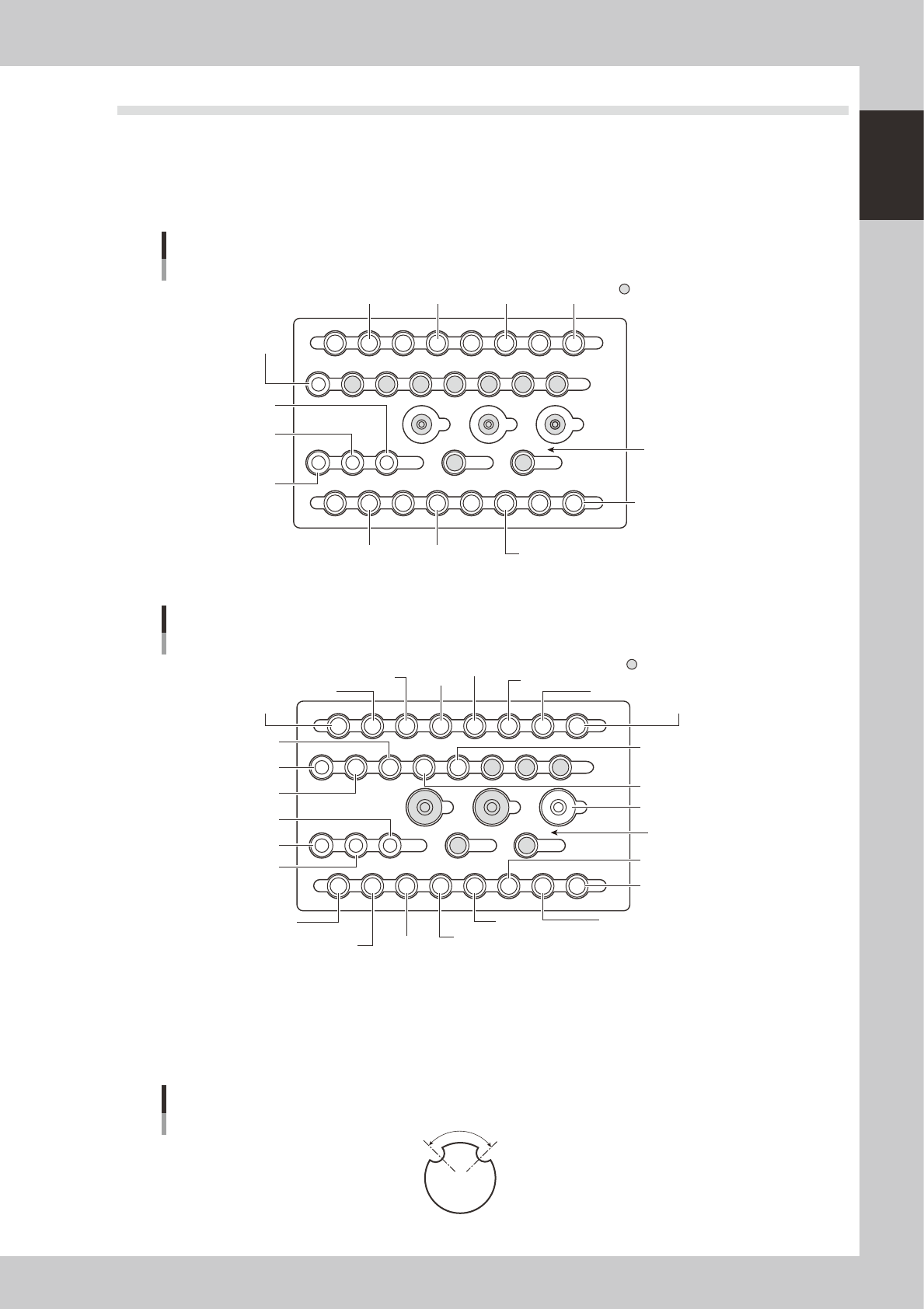
The drawings below show the nozzle station No. and the allotted head No. and mating nozzle type.
YG100R nozzle station
For FNC type
13141516
17
20
252627
28
29303132
21222324
1819
9101112
5678 1234
HEAD1
TYPE 211A
HEAD5
TYPE 214A
HEAD7
TYPE 214A
HEAD1
TYPE 212(219)A
HEAD3
TYPE 212(219)A
HEAD5
TYPE 212(219)A
HEAD7
TYPE 212(219)A
HEAD3
TYPE 214A
HEAD1
TYPE 214A
HEAD3
TYPE 211A
HEAD5
TYPE 211A
HEAD7
TYPE 211A
Custom nozzle pockets
Station No.
23113-M1-00
YG100R nozzle station
For standard type
13141516
17
20
252627
28
29303132
21222324
1819
9101112
5678 1234
HEAD1
TYPE 211A
HEAD1
TYPE 215A
HEAD2
TYPE 211A
HEAD5
TYPE 214A
HEAD7
TYPE 214A
HEAD6
TYPE 213A
HEAD2
TYPE 213A
HEAD4
TYPE 213A
HEAD8
TYPE 213A
HEAD2
TYPE 212(219)A
HEAD1
TYPE 212(219)A
HEAD3
TYPE 212(219)A
HEAD4
TYPE 212(219)A
HEAD5
TYPE 212(219)A
HEAD6
TYPE 212(219)A
HEAD7
TYPE 212(219)A
HEAD8
TYPE 212(219)A
HEAD3
TYPE 214A
HEAD1
TYPE 214A
HEAD3
TYPE 211A
HEAD4
TYPE 211A
HEAD5
TYPE 211A
HEAD7
TYPE 211A
HEAD8
TYPE 211A
HEAD6
TYPE 211A
Custom nozzle pockets
Station No.
23112-M1-00
n
Nozzle notch angle
The nozzles for the YG100R have notches as shown below for identifying their position in the station. The
q
(theta) angle
here is called the notch angle. The notch angles on Type 211A and Type 212A nozzles are respectively 90 and 60
degrees. The notches on the special nozzles 213A and 215A are 120 degrees.
Nozzle notch angle
Q
23116-M1-00
1-10
1
Part names and functions
4. Component supply section
Components or parts are supplied from tape feeders installed on a feeder plate or from an external tray
changer or tray stacker. Under each feeder plate in the feeder setup section, power supply connectors and
air connectors are provided for driving optional units.
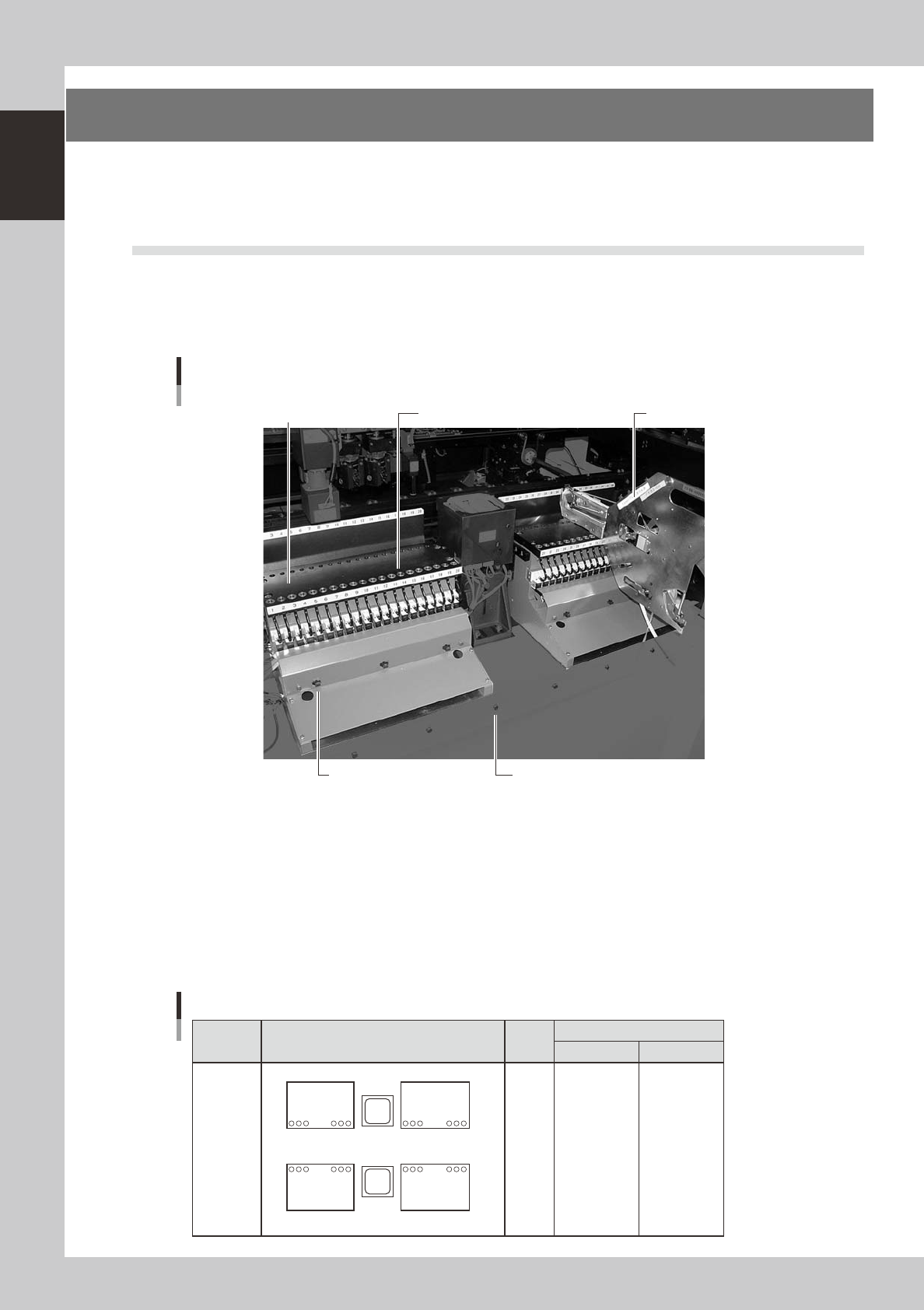
4.1 Supplying components from feeder plates
4.1.1 Fixed feeder plates
Tape feeders, bulk feeders and stick feeders are installed on the feeder plates, and operate by air supplied from
the mounter.
Feeder plate
Feeder drive air outlet
Feeder plate
Power supply connector
Air connector
Tape feeder (option)
23108-M1-00
Power supply connector
When using optional units such as stick feeders, plug the power cord into this connector.
Air connector
When using optional units such as stick feeders and air gun, connect the air tube (O.D. 4mm) to this air connector. Air is
supplied from the mounter to the connected unit. The feeder plate layout and set numbers differ depending on the
machine specifications. Typical feeder plate layouts are shown below. Some feeders cannot be reached by a head
depending on the head assembly configuration and X-axis movement range. The tables below show feeder set numbers
that can be accessed by each head.
1
2
3
4
5
6
7
8
8 to 48
7 to 47
6 to 46
5 to 45
4 to 44
3 to 43
2 to 42
1 to 41
101 to 141
102 to 142
103 to 143
104 to 144
105 to 145
106 to 146
107 to 137
108 to 148
1
24
25
48
148
125
124
101
Set No.
Layout
Head
No.
Type
Front Rear
Feeder plate layout
Quick
feeder
plate
exchange
carriage on
both sides
23109-M1-00
1-11
1
Part names and functions
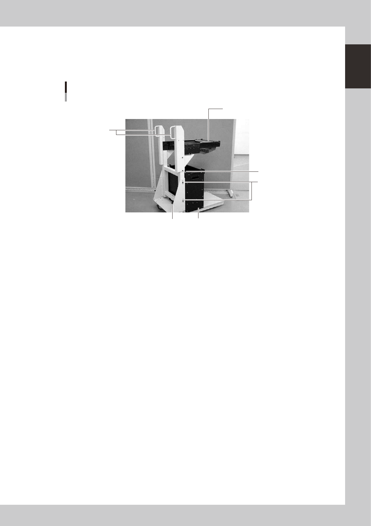
4.1.2 Feeder exchange carriage
The feeder exchange carriage allows feeder setup in advance for the next production boards. The feeders on
the feeder exchange carriage can be changed at one time.
n
Feeder exchange carriage
External view of feeder exchange carriage
1
2
5
4
6
3
23118-M1-00
1 Handle
Use this handle to move and position the feeder exchange carriage.
2 Feeder plate
Up to 20 or 24 tape feeders (8mm tape feeders) can be installed on this feeder plate.
3 Vertical clamp bolts
If necessary to adjust the feeder plate height, loosen these bolts and change their clamping positions by turning the
height adjustment bolt 6 to match the mounter height.
4 Empty tape dump box (option)
This box is for catching empty tape after components have been picked up.
5 Empty tape dump box holder
This holder prevents the tape dump box (option) from falling.
6 Height adjustment bolt
After loosening the vertical clamp bolts 3, turn this bolt to adjust the feeder plate height to match the mounter height.