YSM10_Mainte_E.pdf - 第63页
2-4 2 Daily maintenance items 1.1.1 V acuum level when nozzle is open T he table below shows the vacuum lev el measured when each nozzle is open. T he values might differ slightly depending on the air source and operatin…
2-3
2
Daily maintenance items
n
How to check for clogged nozzles (on the [Unit] - [Head] tab screen)
The term "clogged nozzle" used here indicates that material such as solder is adhering to the nozzle hole, causing a rise
in negative pressure even if no component is being picked up by the nozzle. This state might cause problems such as
component mounting errors. Check for clogged nozzles with the following procedure using the Type 302A as an example.
n
NOTE
When checking other nozzles and their vacuum levels, see the next section "1.1.1 Vacuum level when nozzle is
open"in this chapter.
e
1
Replace the nozzle.
n
Without nozzle station
1. Press the emergency stop button to open
the machine safety cover.
2. Attach Type 302A nozzles to all the
heads.
n
With nozzle station
Press the [Nozzle Change] button to attach
Type 302A nozzles to all the heads.
54202-KMG-00
2
Reset the numerical value.
Open the [Unit] - [Head] tab screen. Then
press the [Reset] button on the lower right of
the screen to reset the vacuum level values.
3
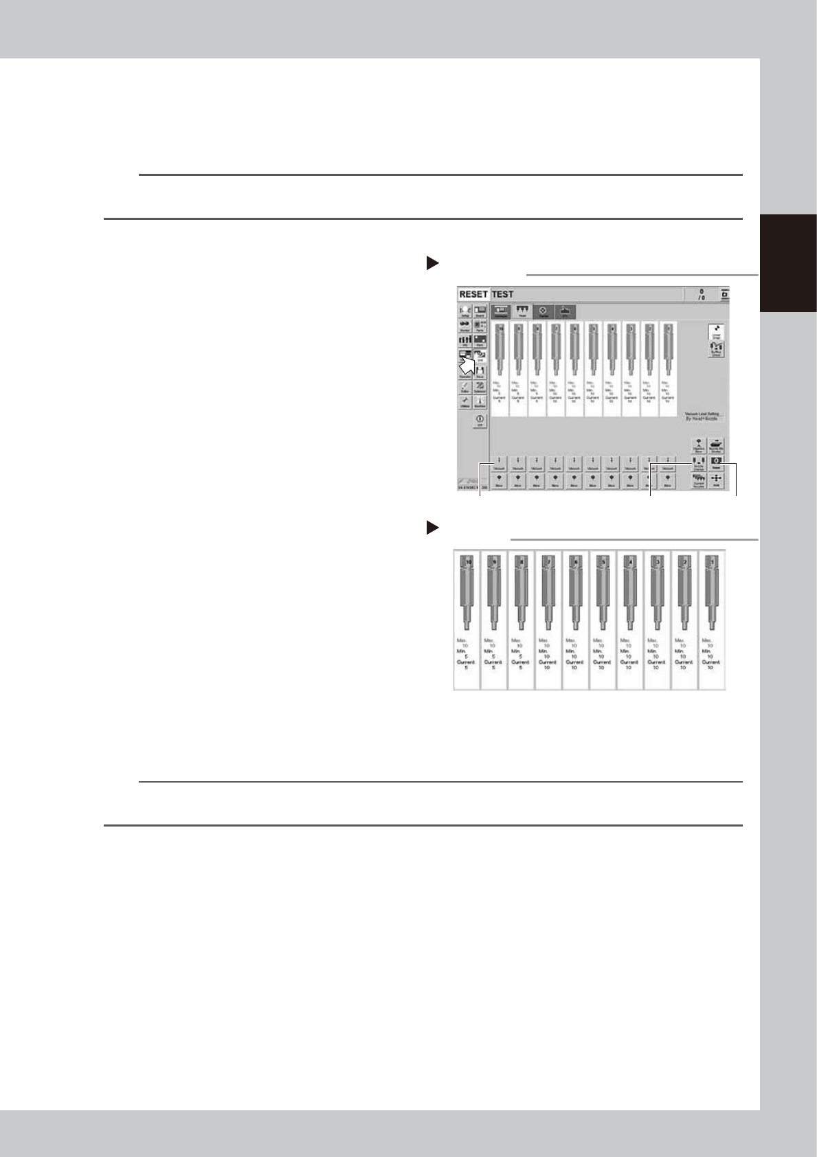
Generate negative pressure.
On the [Unit] - [Head] tab screen, set the
[Vacuum] buttons for all heads to ON. When
this value starts rising, wait 5 to 10 seconds
and set to OFF.
4
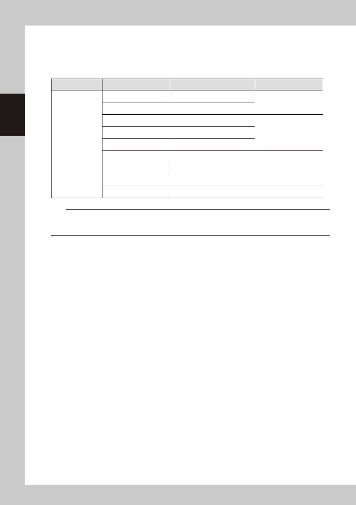
Check the vacuum levels.
Change the all "Max" values shown in red on
the [Head] tab screen. When using Type 302
nozzle and this value is 60 to 110, it is in the
normal range. If higher than 110, the nozzle
hole might be dirty. Clean the nozzle while
referring to "1.2 Nozzle cleaning"in Chapter
3.
54203-KMG-00
n
NOTE
If a correct value cannot be obtained by performing steps 1 to 4 after cleaning the nozzle, the inside of the spline
shaft might be not clean. See chapter 3, "5.1.1 Cleaning the spline shaft"to clean it.
Negative pressure generation
Step 1 to 3
[Nozzle Change] button
[Vacuum] button [Reset] button
Negative pressure check
Step 4
2-4
2
Daily maintenance items
1.1.1 Vacuum level when nozzle is open
The table below shows the vacuum level measured when each nozzle is open.
The values might differ slightly depending on the air source and operating conditions. Use these values for
reference during maintenance.
n
Standard vacuum level when nozzle is open
Head Type Nozzle Standard value when nozzle is open Remarks
Common to HM /
HM5 head units
Type301A 150 to 190
Standard nozzle
Type302A 60 to 110
Type311A 150 to 190
Narrow-pitch nozzleType312A 130 to 180
Type313A 40 to 80
Type303A/Type314A* 40 to 80
Standard and Narrow-pitch
common nozzle
Type304A/Type315A* 30 to 60
Type307A/Type318A* 30 to 60
No nozzle 30 to 60
n
NOTE
The nozzle holes of the nozzles marked with an asterisk are larger than those of other nozzles. If a nozzle marked with
an asterisk exceeds its standard value shown above, the air path in the head (spline shaft, etc.) may be
contaminated.
2-5
2
Daily maintenance items
1.2 Checking the nozzles visually
To visually check nozzles, remove each nozzle from the head or from the nozzle station.
n
NOTE
As for a simple method, check the nozzle attached to the head with a mirror or similar tool.
n
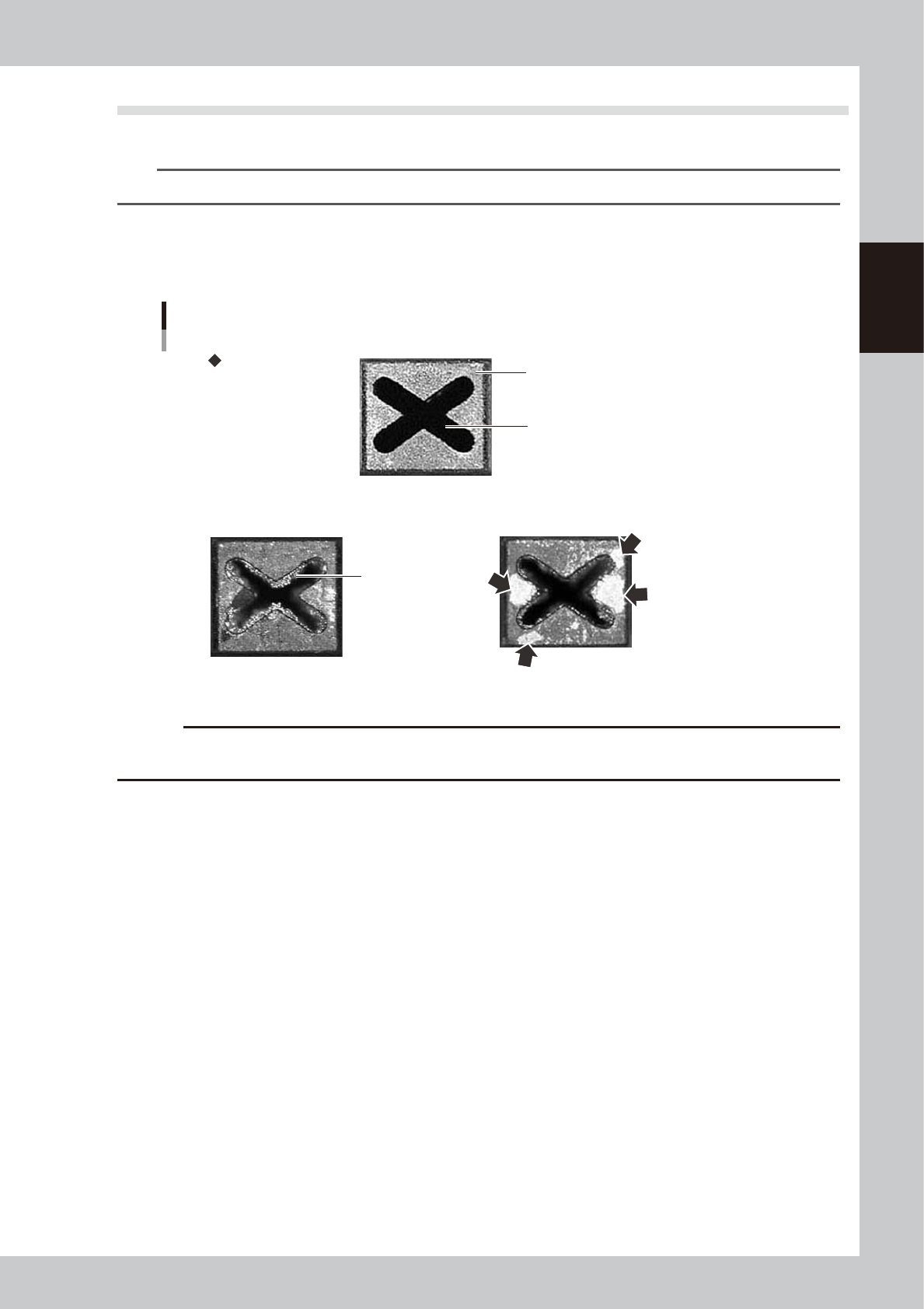
Points to check the removed nozzles
Check the removed nozzles with a magnifying glass or similar tool.
If any solder or contaminant sticks to the nozzle tip or nozzle hole, clean the nozzle.
Nozzle tip
Solder is adhering to
nozzle hole.
Solder is adhering to
nozzle tip (flat surface).
Nozzle hole
Checking the nozzle condition
Fail: Nozzle is clogged. Fail: Shiny material is on tip.
Normal condition
53200-KMG-00
c
CAUTION
If the above check reveals a clogged or dirty nozzle, clean the nozzle hole or nozzle tip by referring to section "1.2
Nozzle cleaning" in Chapter 3.
n
Checking nozzles by removing them from the head
1. Move the head to a position where the nozzles can be easily removed, then remove each nozzle by hand.
2. After checking and cleaning the nozzle, reattach the nozzle to the head while making sure the head position and the
nozzle's orientation are correct.
n
Checking nozzles by removing them from the nozzle station
1. Return all nozzles in the nozzle station.
2. On the [Unit] - [Head] tab screen, press the [Nozzle Stn Shutter] button to allow the nozzles to be removed from the
nozzle station, then remove each nozzle by hand.
3. Check and clean the nozzle.
4. Return the nozzle back at the nozzle station and press the [Nozzle Stn Shutter] button again.