YSM10_Mainte_E.pdf - 第75页
3-8 3 Periodic maintenance items 1.3 Recognition unit 1.3.1 Cleaning the multi-camera lighting's protective glass Adhered dust, etc., on the multi-camera lighting's protecti ve glass can cause component recogni…
3-7
3
Periodic maintenance items
n
How to use ANC nozzle attaching / detaching tool (attaching nozzles)
Attach nozzles at the nozzle station in the reverse order of detaching.
1
Check the nozzle setting position.
Check that other nozzles are not set to the nozzle storage position and the setting position is correct.
n
NOTE
Regarding the nozzle setting position, check the nozzle placement position label attached in the machine or the
machine setting.
2
Set the nozzles to the tool.
c
CAUTION
The positioning pins are in each nozzle storage position at the nozzle station to avoid setting the incorrect types of
nozzle and the incorrect nozzle setting direction. Take precautions about the nozzle setting position and the nozzle
setting direction when setting the nozzles to the tool.
3
Open the nozzle station shutter.
1. Press the emergency stop button to open the machine safety cover.
2. Open the [Unit] - [Head] screen and press the [Nozzle. Stn Shutter] button to open the nozzle station
shutter.
4
Set the tool on the nozzle station.
1. Set the tool that the nozzles were set in Step 2 to the relevant position of the nozzle station.
2. Check that the nozzles are set securely to the nozzle station.
5
Close the nozzle station shutter.
Press the [Nozzle. Stn Shutter] button again and close the nozzle station shutter.
6
Raise the tool up.
Raise the tool up vertically and slowly and detach the nozzles from the tool.
n
NOTE
Raise the tool up vertically and slowly to avoid the nozzle tip from hitting the shutter, etc.
c
CAUTION
If raising the tool up fast and forcibly, nozzles or the nozzle station may be damaged.
3-8
3
Periodic maintenance items
1.3 Recognition unit
1.3.1 Cleaning the multi-camera lighting's protective glass
Adhered dust, etc., on the multi-camera lighting's protective glass can cause component recognition errors. To
prevent this, it is recommended to inspect and clean the cover in a periodic manner.
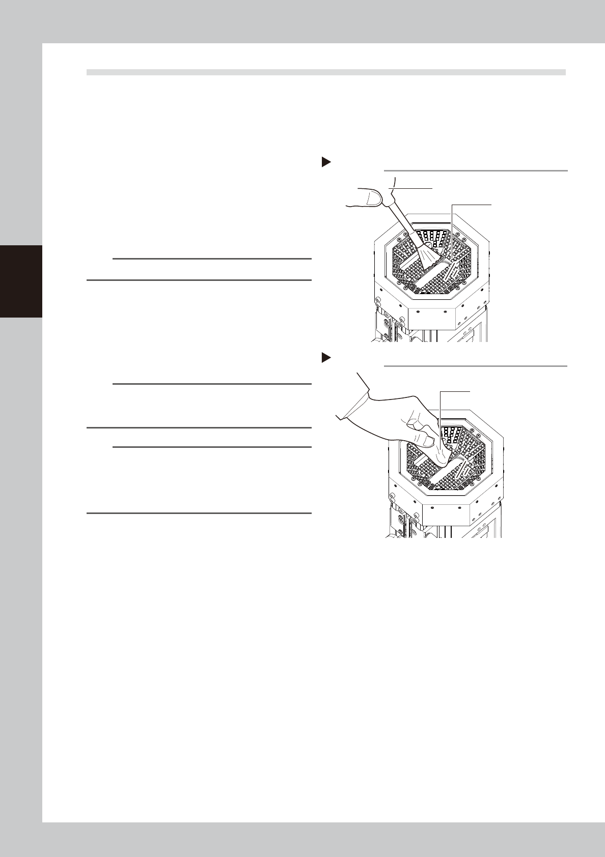
1
Blow off dust on the lighting's
protective glass.
1. Press the emergency stop button to open
the machine safety cover.
2. Remove the dust on the lighting's
protective glass with a blower brush.
53310-KMG-00
TIP
A blower brush is available as an option.
2
Wipe the lighting's protective glass
with a cloth.
Wipe the lighting's protective glass with a
cloth which has been dampened with a
small amount of lens cleaner.
53311-KMG-00
n
NOTE
Use a lint-free cleaning cloth or paper wiper.
A lens cleaner is supplied with the machine. Do not use
other type of cleaner.
n
NOTE
If contaminants cannot be removed completely even
after performing the work stated above, clean the
backside of the protective glass or the lighting referring
to "4.1.2 Cleaning the multi-camera lighting unit" in this
Chapter.
Step 1
Blowing off dust with blower brush
Protective glass
Blower brush
Step 2
Wiping lighting's protective glass with lint-free cloth
Lint-free cloth
3-9
3
Periodic maintenance items
2. Monthly inspection
This section mainly describes the procedures of inspecting, cleaning and lubricating the X, Y axes ball screw
and the guide. The inspection items and cautions of X, Y axes are given below.
n
Inspection items
1. Any foreign matter adhering to the ball screws and linear guides?
Check if any fallen chips have adhered to the X and Y axis ball screws and/or X, Y and W axis linear guides.
2. Do the ball screws and linear guides have the correct amount of grease?
Check if grease has flowed off or splattered in the air failing to adhere. Also check if grease has discolored or hardened.
e
3. Any abnormal sounds from the ball screws?
Press the emergency stop button. Push the X-axis or Y-axis manually to check that they move smoothly and no abnormal
sounds are heard.
Countermeasures
1. Ball screws and linear guides may be damaged when chips and other material bite into them. If chips are adhering,
wipe them off along with the grease or remove with tweezers, etc.
2. Apply grease while referring “Cleaning and lubrication” described later on.
3. Consult your YAMAHA sales office or representative when abnormal sounds occur even after trying the
countermeasures in the above steps 1 and 2.
n
Cautions
w
WARNING
THE HEAD UNIT OF THE MACHINE CONTAINS PARTS GENERATING STRONG MAGNETIC FIELDS. GREAT CARE SHOULD BE
TAKEN WHEN A PART OF YOUR BODY IS PUT INSIDE THE MACHINE FOR THE MAINTENANCE WORK. CAUTIONS REGARDING
FERROMAGNETIC FIELDS ARE DESCRIBED IN THE SECTION, "SAFETY INSTRUCTIONS", AT THE BEGINNING OF THIS
DOCUMENT. ALWAYS THOROUGHLY READ THIS SECTION TO FULLY UNDERSTAND ITS CONTENTS.
c
CAUTION
If abnormal noise is emitted from the ball screw or linear guide of each axis ball screw or linear guide, then contact
our sales representative for assistance. Disassembly and cleaning of the ball screw or linear guide by the user will void
the warranty.
c
CAUTION
When performing the cleaning and greasing work, use square cloth to prevent parts from being lost.
c
CAUTION
When handling grease, read the safety precautions stated in "Safety instructions" and "2.3.2 Lubricating tools and
grease" in Chapter 1.