YSM10_Mainte_E.pdf - 第85页
3-18 3 Periodic maintenance items 3. Three-month inspection This section describes the maintenance work perfor med once every 3 months. 3.1 Head unit 3.1.1 Cleaning and replacing the air filter As a general guideline, th…
3-17
3
Periodic maintenance items
4
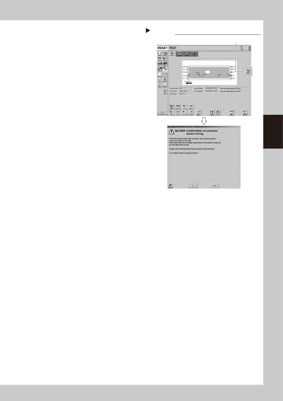
Perform the conveyor sensor
tuning.
1. If an error occurred, press the [Sensor
Tune] button on the right of the [Unit] -
[Conveyor] tab screen.
2. If pressing the [OK] button on the
confirmation screen, the threshold value
is calculated as the current sensor status
is no board.
54302-KMG-00
5
Check the sensor status.
Change the conveyor width again and
check that no error message appears.
6
Check the portion around the
sensor.
If the error message still appears, the light
receiving status around the sensor may be
poor, the sensor (amplifier) may be
malfunction, or the fiber may be broken.
First, remove contaminant or dust from the
sensor, then perform the conveyor sensor
tuning again.
Conveyor sensor tuning
Step 4
[Sensor tuning] button
3-18
3
Periodic maintenance items
3. Three-month inspection
This section describes the maintenance work performed once every 3 months.
3.1 Head unit
3.1.1 Cleaning and replacing the air filter
As a general guideline, the filter should be inspected once every 3 months, although this may vary somewhat
depending on the air supply conditions and the operating time. If lightly soiled, the filter can be clean by using
the air blow tool. The filter should be replaced when it can no longer be adequately cleaned by air-blowing.
n
NOTE
The procedure of HM head unit is described as example. The procedure of HM5 head unit is also the same.
1
Prepare for the work.
e
1. Press the emergency stop button to open
the machine safety cover.
2. Move the head unit forward.
3.
Place a square cloth under the head unit
.
2
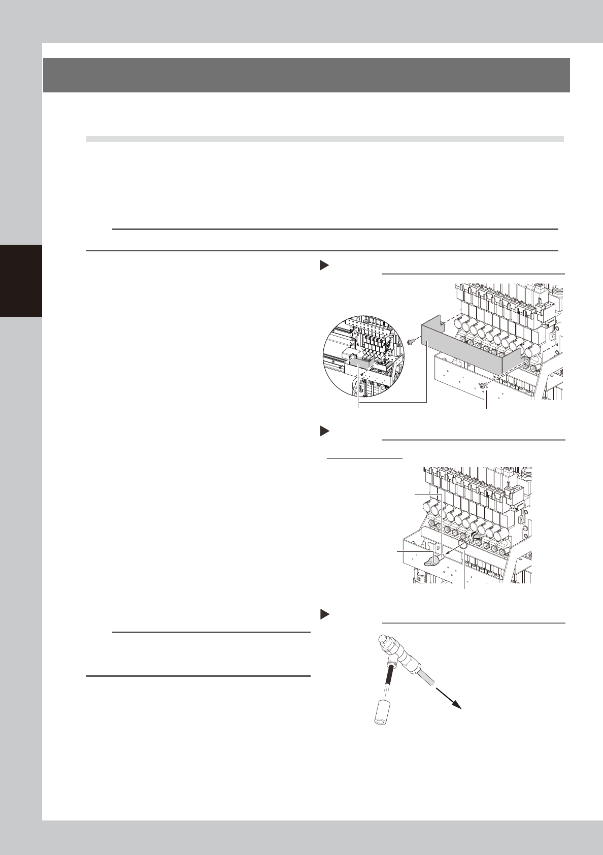
Detach the baffle plate.
Remove the 2 screws mounting the baffle
plate with a phillips screwdriver.
53325-KMG-00
3
Remove the filter.
Turning the filter cap left will remove it
together with the filter.
53326-KMG-00
4
Clean the filter.
If the filter is only lightly soiled, it can be
cleaned by the air blow tool, and then
reused.
If the filter is badly soiled or discolored,
replace it with a new one.
5
Reattach the filter.
1. Fit the filter into the filter cap.
2. Insert the filter cap into its original
position and turn it right to mount it.
53327-KMG-00
n
NOTE
When attaching the filter, check also the status of the
filter gasket. If the gasket deteriorates or is deformed,
replace it with a new one.
6
Reattach the baffle plate.
1. Reattach the baffle plate.
2. Remove the square cloth.
Step 3
Example of HM head
Filter gasket
Removing the filter
Filter cap
Filter
Step 2
Mounting screw (2 locations)
Removing the baffle plate
Baffle plate
HM5 head
HM head
Cleaning the filter
Step 4
Filter
Air blow tool
To air connector
3-19
3
Periodic maintenance items
3.2 PU-axis
The PU (push-up) axis is designed to prevent flexing or warping of the board during clamping and is important
because it prevents depressing of the board during component mounting.
The PU-axis also prevents deviations in the component mounting accuracy due to the board depressing during
component mounting, so it is important to regularly clean and inspect the PU-axis to ensure it operates
correctly.
c
CAUTION
If trouble occurs with the PU-axis, then contact our sales representative for assistance. Disassembly and cleaning of
the PU-axis by the user will void the warranty.
3.2.1 Cleaning and lubricating the PU-axis ball screw and guide
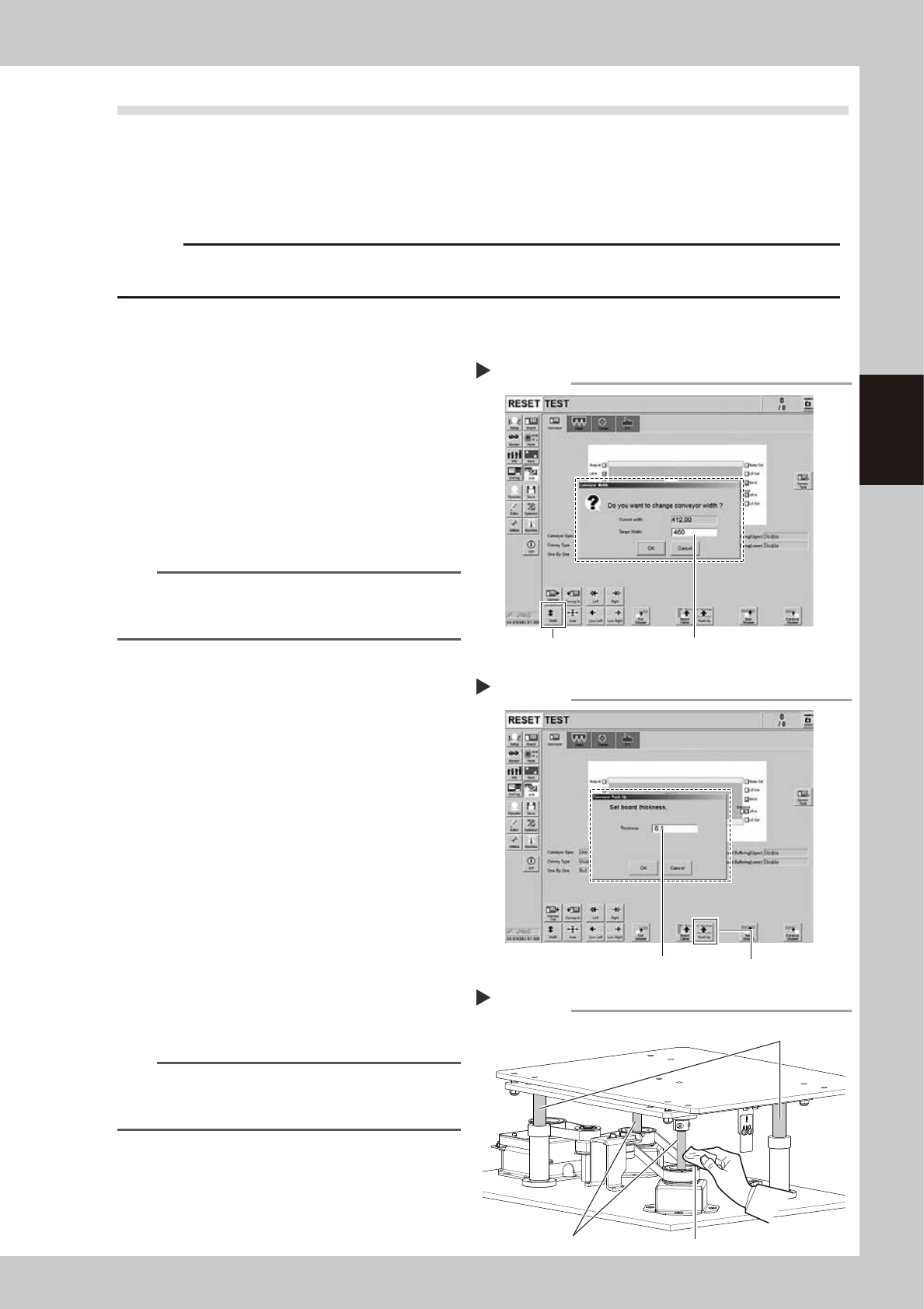
1
Change the conveyor width to its
maximum width.
1. Press the [Width] button on the [Unit]
- [Conveyor] tab screen to display the
"Conveyor Width" screen.
2. Enter the maximum value of the
conveyor width in the "Target Width" field
and press the [OK] button. The conveyor
width is changed to the specified width.
54303-KMG-00
TIP
The maximum conveyor width is 460 mm as a standard
feature. If the machine is equipped with sATS15, the
maximum width is 360 mm.
2
Raise the PU-axis.
1. Press the [Push Up] button on the [Unit]
- [Conveyor] tab screen to display the
"Conveyor Push Up" screen.
2. Enter "0.1 mm" in the "Thickness" field and
press the [OK] button. The PU-axis is
raised.
54304-KMG-00
3
Clean the ball screws and the ball
guides.
e
1. Press the emergency stop button to open
the machine safety cover.
2. Move the head unit backward.
3. Wipe the entire ball screws and ball
guides (2 positions each) with a lint-free
cloth or paper towel (for clean room
use).
53328-KMG-00
n
NOTE
When cleaning the ball screw, carefully clean its
groove area as well. Be sure that the cloth, etc., being
used to clean the ball screw does not produce lint, etc.
Step 3
Cleaning ball screws and ball guides
Cloth
Ball screw
Ball guide
Step 1
Enter the maximum conveyor width.[Width] button
Changing the conveyor width
Raising PU-axis
Step 2
[Push Up] buttonEnter 0.1 mm as board thickness.