A10011-ASM-T45-EN-Spec-E_DMS.pdf - 第10页
10 Placement Heads SIPLACE CP12 SIPLACE CP12 with component came ra type 30 GigE Range of components a a) Please note that the component range that can be placed is also affected by the pad geometry, the customer-specifi…
9
Placement Heads
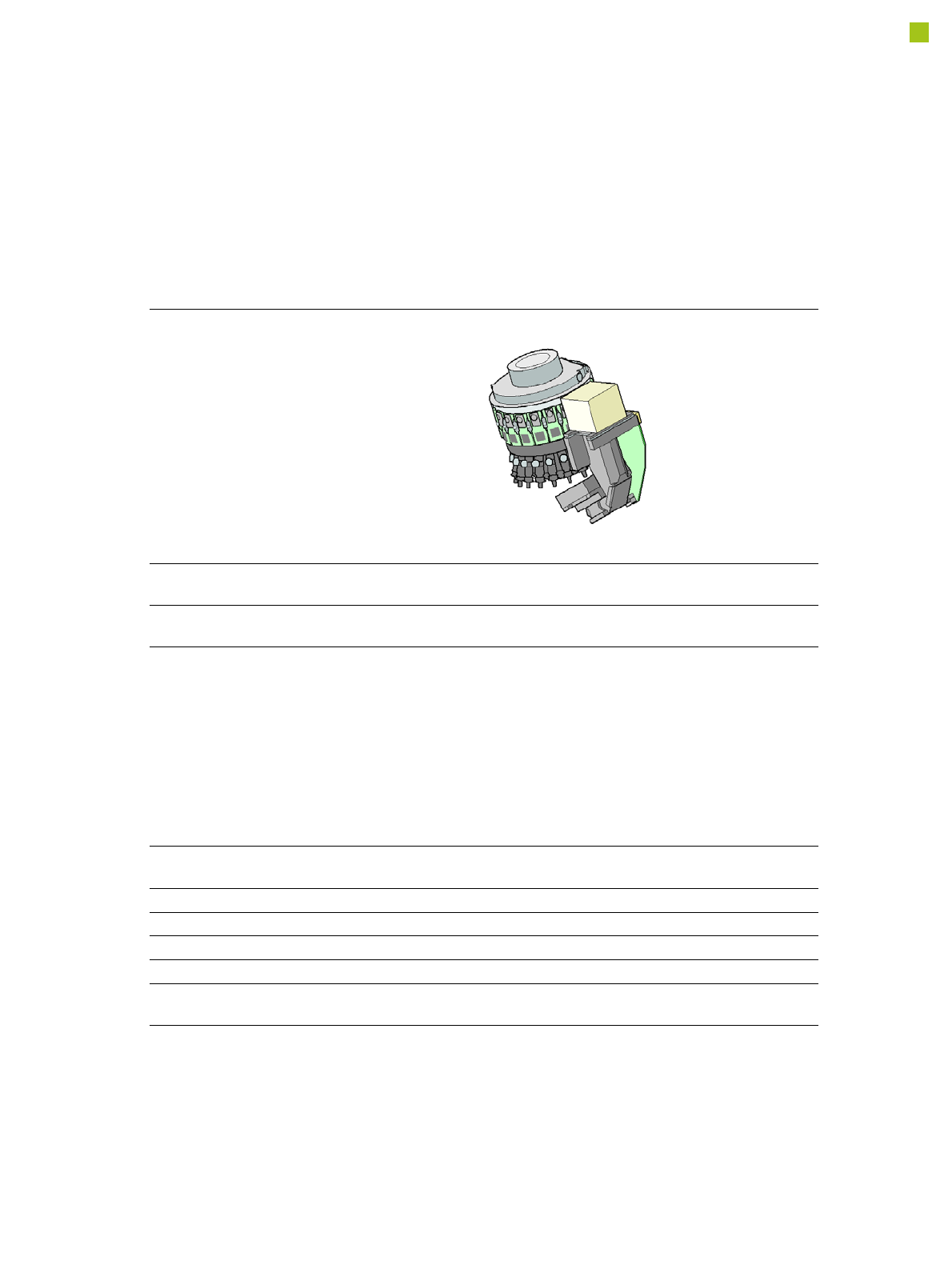
SIPLACE CP14
SIPLACE CP14
with component camera type
23 GigE
Component range
a
a) Please note that the placeable component range is also affected by the pad geometry, the customer-spe-
cific standards, the component packaging tolerances and the component tolerances.
01005 to 2220, Melf, SOT,
SOD
Component spec.
Max. height
Min. lead pitch
Min. lead width
Min. ball pitch
Min. ball diameter
Min. dimensions
Max. dimensions
Max. weight
4 mm
0.25 mm
0.1 mm
0.4 mm
0.2 mm
0.4 mm x 0.2 mm
6 mm x 6 mm
1.0 g
Programmable set-down
force
1.3 - 4.5 N
Nozzle types 4xxx
X/Y accuracy
b
b) The SIPLACE accuracy value is measured during the machine acceptance tests. It corresponds to the
conditions set out in the SIPLACE scope of service and supply.
± 41 µm/3σ
Angular accuracy ± 0.5° / 3σ
Illumination level 5
Possible illumination
level settings
256
10
Placement Heads
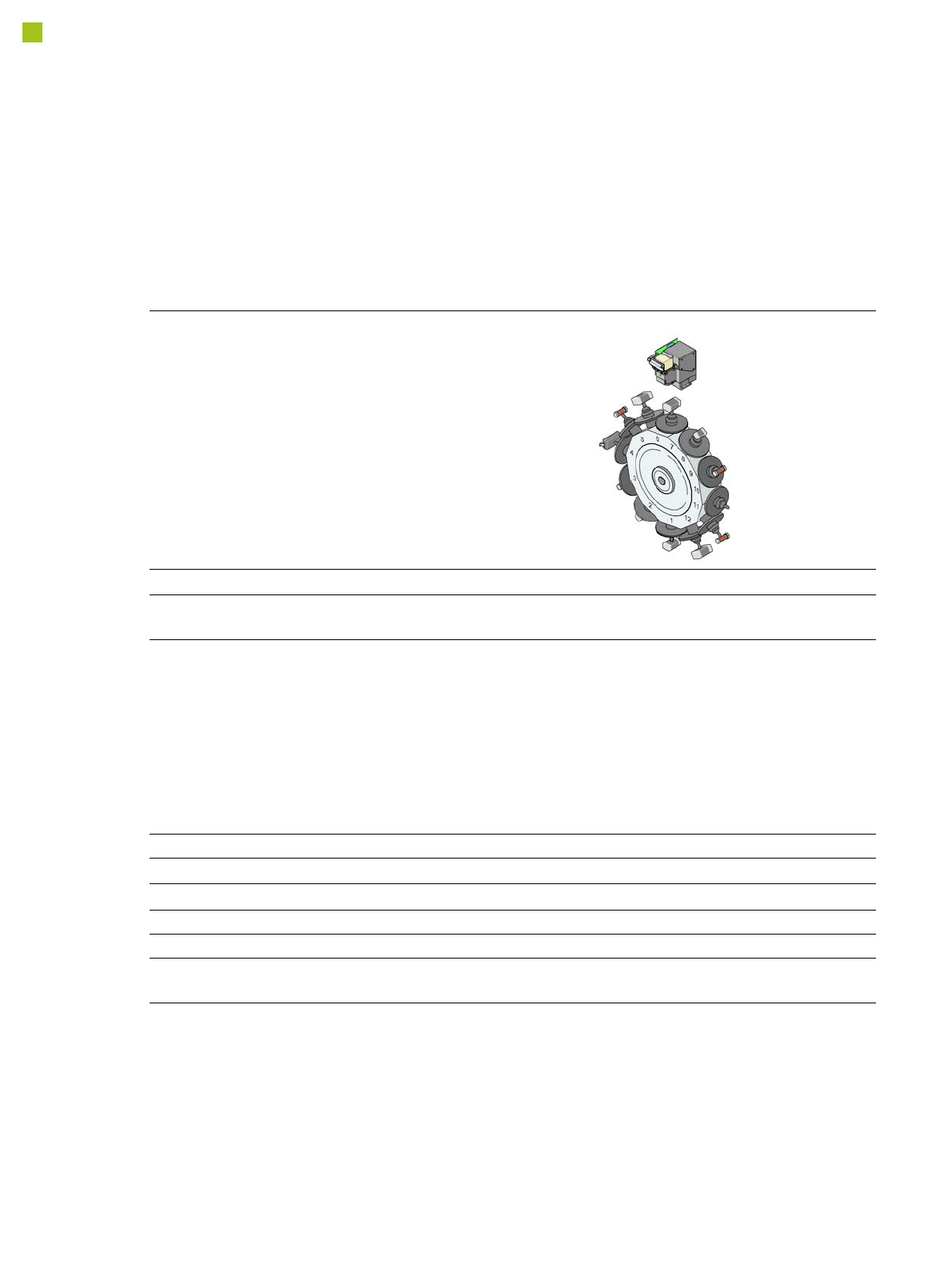
SIPLACE CP12
SIPLACE CP12
with component camera type 30 GigE
Range of components
a
a) Please note that the component range that can be placed is also affected by the pad geometry, the customer-specific
standards and the packaging tolerances.
01005 to flip-chip, bare die, PLCC44, BGA, µBGA, TSOP, QFP, SO to
SO32, DRAM
Component specification
Max. height
Min. lead pitch
Min. lead width
Min. ball pitch
Min. ball diameter
Min. dimensions
Max. dimensions
b
Max. weight
b) For high volume 01005-placement it is recommended to equip the CP12 with its optional 01005-package that con-
tains special nozzles and low force segments.
8.5 mm
c
0.3 mm
0.15 mm
0.25 mm
0.14 mm
0.4 mm x 0.2 mm
18.7 mm x 18.7 mm
2 g
c) 8.5 mm on Flex machines, 7.5 mm on Speed machines.
Nozzle types 30xx
X/Y accuracy
d
d) The accuracy value was measured using the vendor-neutral IPC standard.
± 41 μm/3σ
Angular accuracy ± 0.5°/3σ
Component range 98.5%
Illumination levels 5
Possible illumination level
setting
256
11
Placement Heads
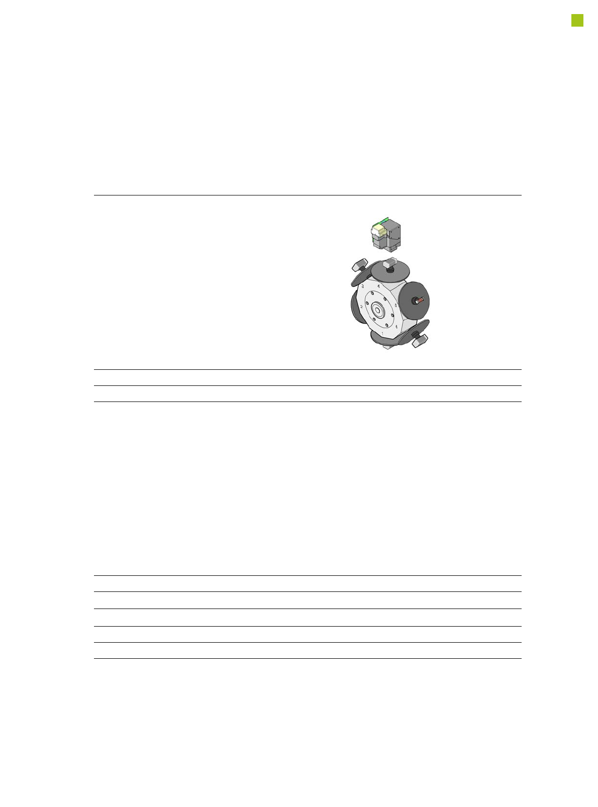
SIPLACE CP6
SIPLACE CP6
with component camera, type 30 GigE
Range of components
a
a) Please note that the component range that can be placed is also affected by the pad geometry, the custom-
er-specific standards and the packaging tolerances.
0201 to 27 x 27 mm²
Component specification
Max. height
Min. lead pitch
Min. lead width
Min. ball pitch
Min. ball diameter
Min. dimensions
Max. dimensions
Max. weight
8.5 mm
b
0.3 mm
0.15 mm
0.25 mm for components< 18 mm x 18 mm
0.35 mm for components ≥18 mm x 18 mm
0.14 mm for components < 18 mm x 18 mm
0.2 mm for components ≥ 18 mm x 18 mm
0.6 mm x 0.3 mm
27 mm x 27 mm
5 g
b) 8.5 mm on Flex machines. No Speed machine configuration
Nozzle types 38xx, 39xx
X/Y accuracy
c
c) The accuracy value was measured using the vendor-neutral IPC standard
± 52.5 μm/3σ
Angular accuracy ± 0.225°/3σ
Illumination levels 5
Possible illumination level setting 256