A10011-ASM-T45-EN-Spec-E_DMS.pdf - 第41页
41 SIPLACE Software Suite SIPLACE Station Programming In the SIPLACE Station Programming mode , the user can create a place - ment program (PCB, co m - ponents, component shapes, set up) direc tly at the placement machin…
40
SIPLACE Software Suite
SIPLACE Station Software
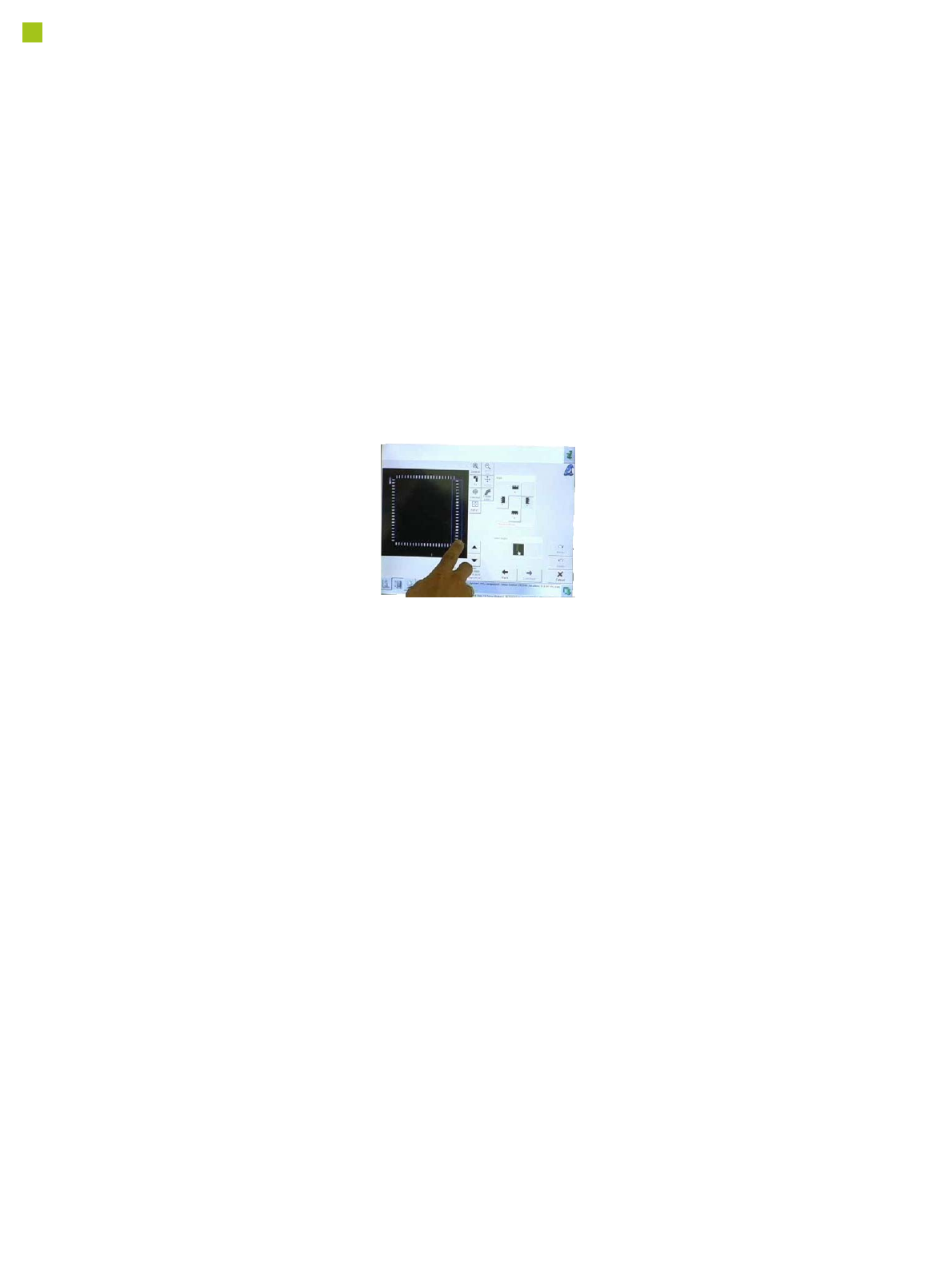
Individual measurement data
The individual measurement
data determined by the
SIPLACE station software
(measurement contexts) can
be saved at the station. This
can be linked to the following
conditions (Vision measure-
ment options):
1. Unable to measure com-
ponent and measurement
data (measurement con-
texts) should be saved.
These measurement data
can then be used for opti-
mization purposes in a
subsequent analysis. As
with other optical inspec-
tion systems, pseudo
errors can be differentiat-
ed from other errors and
the affected component
shape can then be opti-
mized.
2. Vision measurement
logs should always be
written for this compo-
nent.
Whenever there is general
uncertainty about the
quality of a component,
the Vision logs can be writ-
ten for all components.
3. As soon as Vision errors
occur for the component,
the machine will stop.
If you want to avoid com-
ponent rejection, particu-
larly for very expensive
components, this option
can be used to correct all
measurement errors
occurring, without the
need for any rejections.
The machine waits with
the component, in front of
the camera, so that the
component can be
checked.
In addition, pickup and place
positions can be checked
with the PCB camera. This
makes 100% placement con-
trol possible in the machine.
Teaching components
Component shapes which
are not part of the standard
component shape library can
be generated using the
offline programming system
SIPLACE Pro, with the help
of data sheets, or with the
offline Vision teach station
and a sample component.
Alternatively, a component
shape can be marked as
incomplete and transferred
to the station with this status.
The description can be com-
pleted after the first pickup
run on the line.
After completion of the
description, a robustness
analysis can be performed at
the station, to ensure that
this component is always
recognized reliably, even
under different conditions.
You can also program the
placement positions on the
board in the station software.
This software provides
advanced support functions
which allow you, for exam-
ple, to combine images from
the PCB camera with data
from the placement program.
This boosts the productivity
significantly for production
environments with frequent
new production introductions
or product changeovers.
The SIPLACE station soft-
ware makes daily work eas-
ier for users
Many other features in the
station software make day-
to-day work easier for the
users and optimize the SMT
production processes.
• Calibration process con-
trol is fully integrated into
the SW
• Self-repair routines for
nozzles and feeder mod-
ules
• Self-determination of
feeder module cycle
• "Alarms" - at a glance
• "FaceDown" recognition
• Direct access to board
conveyor functions, such
as "nonstop board trans-
port".
41
SIPLACE Software Suite
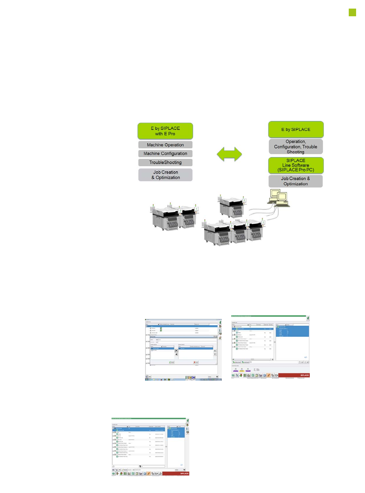
SIPLACE Station Programming
In the SIPLACE Station
Programming mode, the
user can create a place-
ment program (PCB, com-
ponents, component
shapes, setup) directly at
the placement machine.
The specified fiducials and
placement positions are
exactly measured by the
PCB camera.
After a local optimizing run,
the placement process can
be started at the station.
In this case, the placement
machine can be used inde-
pendently without a net-
work connection to a
programming system.
For a manual data exchange,
the placement programs can
be exported from the place-
ment machine or imported
into the placement machine.
In order to implement the sta-
tion programming mode, the
SIPLACE Pro software
including the SQL database
is integrated on the station
computer. The layout of the
SIPLACE Pro GUI has been
adapted to the look and feel
of the station software GUI
and is displayed as SIPLACE
E Pro desktop in the station
software.
Job Editor
The SIPLACE E
Pro provides the
user at the station
with all means that
are required for a
complete descrip-
tion of the place-
ment program.
Line Configuration
Each machine in the network
automatically registers in the
masterPC and is available
for creating a line. Lines can
be: independent machines, a
physical line or a virtual line.
Job Control
Job Control shows the status
of each machine of the cur-
rent line configuration and
manages the correct down-
load to the right machines of
the configured line.
or

42
Technical Data
Electrical Ratings, Energy Consumption and
Compressed Air supply
Electrical ratings
Supply voltage Fuse
Main power supply 3 x 200 V~ up to 3 x 230 V~; ± 10 %; 50/60 Hz)
a
3 x 380 V~ up to 3 x 415 V~; ± 10 %; 50/60 Hz
a) with adapter kit (US option)
3 x 16 A characteristic C
3 x 16 A characteristic C
Mains power connection Cable 4 x 4 mm² with CEKON connector
Energy consumption
Energy consumption
with
vacuum pump
Nominal active power 1.8 kW
Nominal apparent power 2.3 kVA
Compressed air supply
Compressed air pressure values
p
min
p
max
0.5 MPa = 5.0 bar
1.0 MPa = 10 bar
Operating pressure 0.48 MPa ± 0.025 MPa (4.8 bar ± 0.25 bar)
Compressed air connection R 3/4" inner thread (pipe thread) with 1/2" hose connection
Ambient conditions for packaging, transportation and storage
Temperature range Between -25°C and 55°C
Atmospheric humidity Up to 95%
Ambient pressure Up to 3000 m height without pressure equalization
Ambient conditions for machine operation
Room temperature Between 15°C and 35°C
Atmospheric humidity 30% to 75 % (no higher than 45% on average to prevent any possibility of
condensation on the machine)
Ambient pressure > 890 mbar (corresponds to 1000 m above mean sea level)
Compressed air consumption
a
a) Average consumption values
Placement head configura-
tion
Compressed air consumption
b
with
vacuum
pump
c
b) Under normal atmospheric conditions at 20°C and 1013 hPa.
c) Vacuum pump for SIPLACE CP14/CP12/CP6 head only.
E by SIPLACE CP14
CP12
CP12 / PP
CP6 / PP
TH
90 Nl/min
90 Nl/min
140 Nl/min
140 Nl/min
185 Nl/min
Compressed air specification according to DIN ISO 8573-1:2010
Particle size (ISO class 1) 0.1 µm
Particle density (ISO class 1) 0.1 mg/m³
Maximum oil content (ISO class 1) 0.01 mg/m³
Pressure dewpoint (ISO class 4) + 3°