5OM-1840-001w_F8S.pdf - 第57页
5OM-1840 1604-001 1-B

5OM-1840
1604-001 1-A
Chapter 1
Pneumatic and Mounting Diagrams
In this Chapter, the pneumatic and mounting diagrams are described.
As this contains highly sophisticated contents, it should carefully be
referred to.

5OM-1840
1604-001 1-B
5OM-1840
Pneumatic and Mounting Diagrams
1-1-1
1604-001
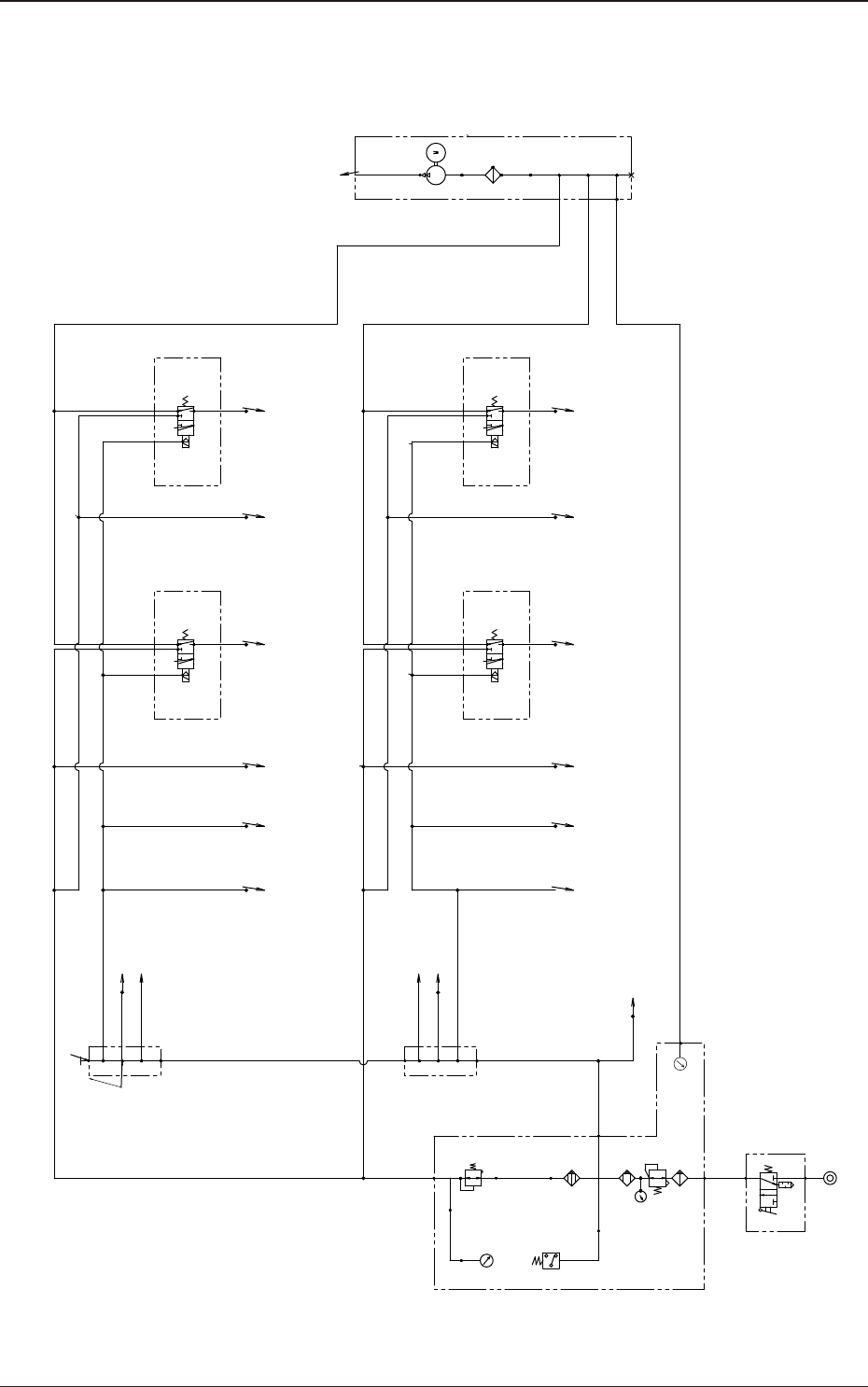
Entire System (Pneumatic Diagram)
A
P
R
Φ10(Blue)
300mm
Positioning(1)
Φ8(Blue)
2000mm
Head(21)
Exhaust
Φ8
Cutter(21)
Cart Bundled
Connector(1)
Φ6
40mm
Φ8
40mm
Φ6
40mm
Φ8(Blue)
720mm
Φ6
770mm
Φ6
400mm
Φ8(Blue)
400mm
Φ6
70mm
Φ10(Blue)
1200mm
Φ6
400mm
Ø8 (Blue)
400mm
Φ6
2000mm
Φ8(Blue)
2000mm
Φ6
150mm
Φ6
70mm
Φ6
70mm
Φ8(Blue)
70mm
Φ6
70mm
Φ6
100mm
Φ6
150mm
Φ6
100mm
Φ6
150mm
Nozzle Stocker
(12)(22)
Nozzle Stocker
(11)(21)
Φ8
40mm
Φ6
150mm
Φ8
100mm
Φ8
950mm
Φ8
700mm
Φ8
1830mm
Φ8
1630mm
Φ8
2450mm
Transfer
(PCB Z Clamp,PCB Stopper)
φ6 (Blue)
1100mm
Φ10(Blue)
2050mm
Φ6
2000mm
Φ8
500mm
Φ6
800mm
KQ2P-10
Φ8
200mm
Φ8
3200mm
Φ10
400mm
Φ10
150mm
Φ8
200mm
Φ8
2600mm
Φ8
350mm
Φ10
120mm
A
Air/Vacuum Mode Change Valve
P
R
Setup
0.05MPa
0.45MPa
(Φ6)
Setup
0.35MPa
Setup
(Φ6)
(Φ8)
A
P
R
A
P
R
Head(21)
Head(22)
Head(22)
Air/Vacuum Mode Change Valve
Air/Vacuum Mode Change Valve
Air/Vacuum Mode Change Valve
Head(11)
Head(11)
Head(12)
Head(12)
Cutter(12)
Cutter(11)
Cart Bundled
Connector(2)
Cutter(22)
Positioning(2)