5OM-1840-001w_F8S.pdf - 第69页
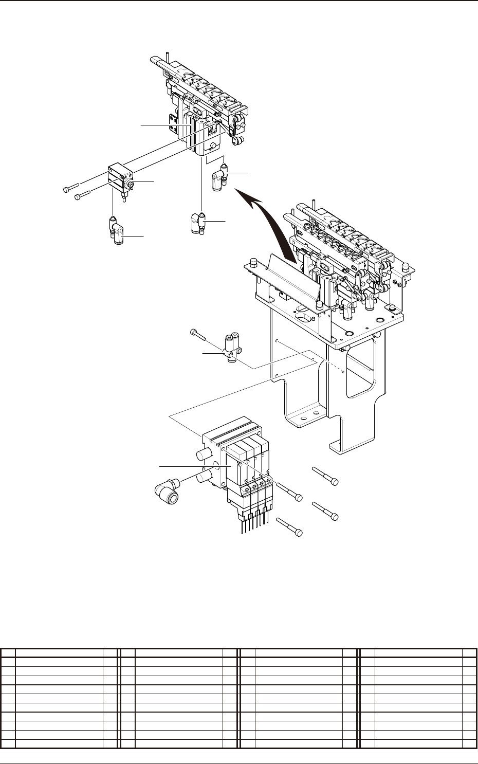
5OM-1840 Pneumatic and Mounting Diagrams 1-1-12 1604-001 Nozzle Stocker (Mounting Diagram) 6 5 7 8 9 7 4 No. Name Q’ty No. Name Q’ty No. Name Q’ty No. Name Q’ty 4 Solenoid Valve 1 5 Cylinder 2 6 Cylinder 2 7 Speed Contro…
5OM-1840
Pneumatic and Mounting Diagrams
1-1-11
1604-001
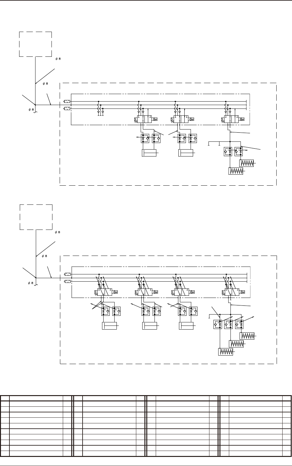
Nozzle Stocker (Pneumatic Diagram)
(03) (03)
(02)
(04)
(03)
(02) (01)
Shutter 3 Open/Close
Stocker 3 U/D
(01)
(02) (01)
3
4A
5
2B
1
Shutter 1 Open/Close
Stocker 1 U/D
Shutter 2 Open/Close
Stocker 2 U/D
3
4A
5
2B
1
Nozzle Stocker(For 2-1,2-2 Areas)
Nozzle Stocker Unit
(For 1-1,1-2 Areas)
Standard Stocker
Deformed Stocker(Option)
3
4A
5
2B
1 3
4A
5
2B
1
From Main Body
400mm
950mm
3
3
3
2
9
9
1
1
(03)
(02)
(03)
(02) (01)
(01)
3
2B
1
4A
5
(04)
Stocker 2 U/D
Shutter 2 Open/Close
Shutter 1 Open/Close
Stocker 1 U/D
From Main Body
400mm
950mm
Nozzle Stocker(For 2-1,2-2 Areas)
3
2B
1
4A
5
3
2B
1
4A
5
3
3
2
1
1
Nozzle Stocker Unit
(For 1-1,1-2 Areas)
No. Name Q’ty No. Name Q’ty No. Name Q’ty No. Name Q’ty
1 Tube
φ
8 1
2 Tube
φ
6 1
3 Tube
φ
4 1
9 Union Y 1
5OM-1840
Pneumatic and Mounting Diagrams
1-1-12
1604-001
Nozzle Stocker (Mounting Diagram)
6
5
7
8
9
7
4
No. Name Q’ty No. Name Q’ty No. Name Q’ty No. Name Q’ty
4 Solenoid Valve 1
5 Cylinder 2
6 Cylinder 2
7 Speed Controller 2
8 Speed Controller 1
9 Union Y 1
5OM-1840
Pneumatic and Mounting Diagrams
1-1-13
1604-001
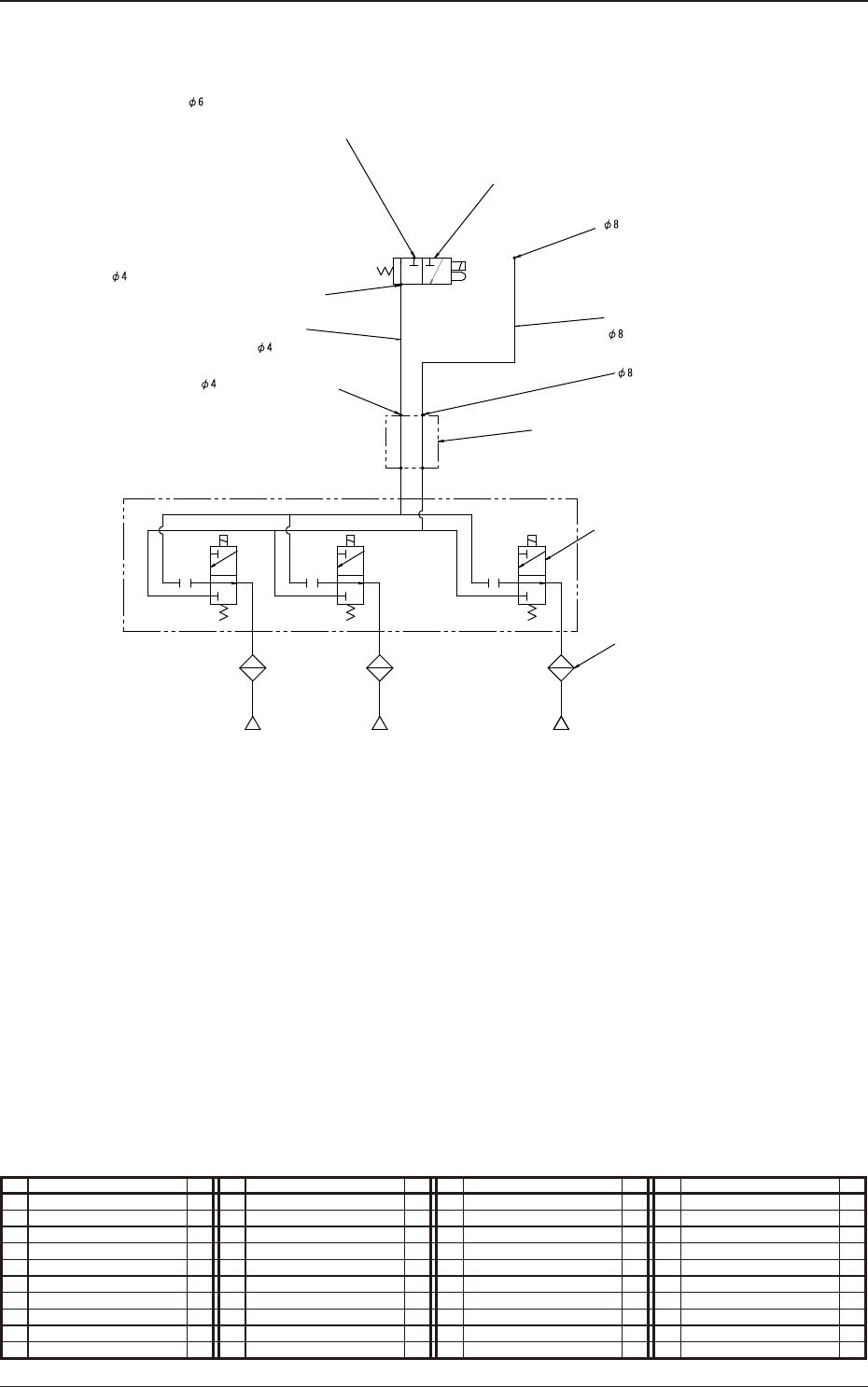
Head Unit (Pneumatic Diagram)
Fitting(KQ2L08-00)
A
V
P
Fitting(KQ2L04-M5)
Rotary Joint(MQR2-01-X154)
Filter
2
3
4
5
6
1
Fitting(KQ2L08-01S)
870mm
830mm
A
V
P
A
R
P
Head
Nozzle 1 Nozzle 15
Valve(VQD1121-5G-X88D)
Nozzle 2
A
V
P
Fitting
High-Speed Head:(KQ2H06-M5)
High-Speed Multi-Purpose Head:(KQ2H06-M5A)
Fitting
High-Speed Head:(KQ2L04-M5)
High-Speed Multi-Purpose Head:(KQ2L04-M5A)
Valve(VQ110U-5L-M5)
No. Name Q’ty No. Name Q’ty No. Name Q’ty No. Name Q’ty
1 Tube
φ
4 1
2 Tube
φ
8 1
3 Solenoid Valve 1
4 Rotary Joint 1
5 Solenoid Valve 15
6 Filter 15