5OM-1840-001w_F8S.pdf - 第73页
5OM-1840 Pneumatic and Mounting Diagrams 1-1-16 1604-001 Feeder Base (Mounting Diagram) 3 2 4 5 6 No. Name Q’ty No. Name Q’ty No. Name Q’ty No. Name Q’ty 2 Solenoid Valve 2 3 Speed Controller 4 4 Cylinder 2 5 Modular Uni…
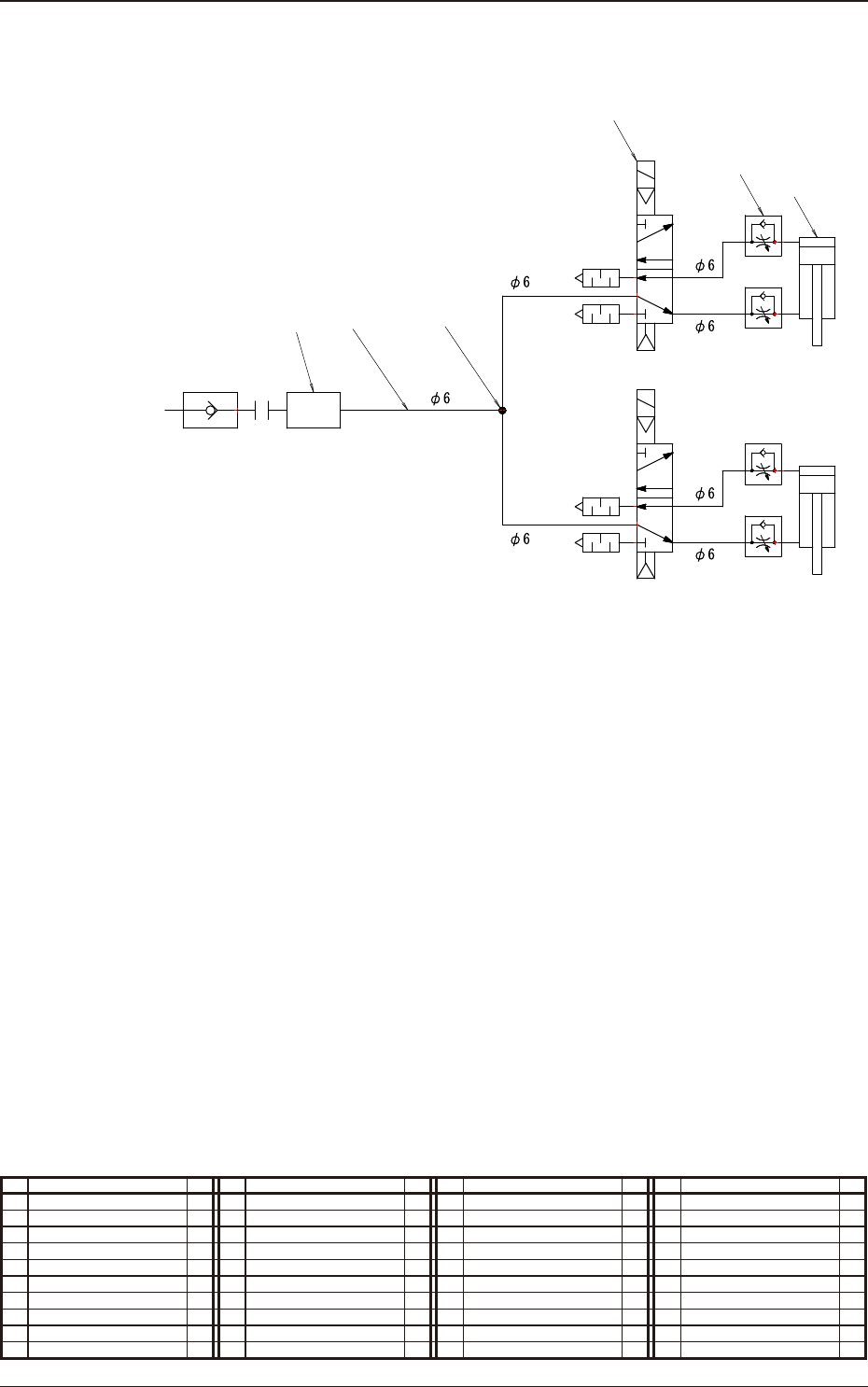
5OM-1840
Pneumatic and Mounting Diagrams
1-1-15
1604-001
Feeder Base (Pneumatic Diagram)
1
7
B
A
B
A
3
2
4
6
5
From Main Body
No. Name Q’ty No. Name Q’ty No. Name Q’ty No. Name Q’ty
1 Tube
φ
6 1
2 Solenoid Valve 2
3 Speed Controller 4
4 Cylinder 2
5 Modular Unit 2
6 Air Connector Pin 2
7 Union Y 1
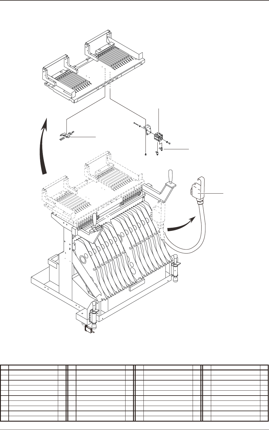
5OM-1840
Pneumatic and Mounting Diagrams
1-1-16
1604-001
Feeder Base (Mounting Diagram)
3
2
4
5
6
No. Name Q’ty No. Name Q’ty No. Name Q’ty No. Name Q’ty
2 Solenoid Valve 2
3 Speed Controller 4
4 Cylinder 2
5 Modular Unit 2
6 Air Connector Pin 2

5OM-1840
1604-001 2-A
Chapter 2
Sensor and Load Layout
This chapter indicates where the sensors and loads are located in each
section.
As this contains highly sophisticated contents, it should carefully be
referred to.