SIPLACE TX V2 micron 设备性能参数_DMS.pdf - 第27页
27 SIPLACE Vision Barcode types Technical data 1D barcode s QR codes Code typ es Code 39 Code 93 Code 128 EAN-8 (AddOn 2, AddOn 5), E AN-13 (AddOn 2, AddOn 5) Interleaved 2 of 5 Minimum width of bar 5 pixels If the quali…

26
SIPLACE Vision
Barcode types
Technical data
The PCB camera can read a
Data matrix code, a 1D bar-
code or a QR code. The
data can be used for trace-
ability purposes.
The barcode can be on the
PCB itself or on a compo-
nent. In addition, it is also
possible to attach a barcode
label to a PCB or a compo-
nent and to then read this
barcode label with the PCB
camera, directly after place-
ment. The focal height must
be taken into account during
reading, if there is a barcode
or barcode label on the top of
a component.
General information for all barcode types
Data matrix codes
Ambiguity No read errors are issued if multiple valid barcode symbols are found in a
particular region of interest (ROI). In this case, there is no clear rule, defin-
ing which of these valid barcode symbols would be read.
Ambiguity can be avoided by:
• Using a suitable ROI size
ASCII null characters Barcode information should not contain any ASCII null characters (ASCII
NULL), as the 0 byte in the software is interpreted as an final (end) char-
acter.
Code type Only data matrix ECC 200 is supported.
No. rows/columns All combinations of rows/columns as defined in the standard will be
accepted, including rectangular symbols and large symbols with multiple
data areas.
Minimum dot size 5 pixels
Symbol angle All symbol angles will be accepted.
Inverse symbols Inverse symbols (light modules on a dark background) will be accepted.
Mirrored symbols Mirrored symbols will be accepted.
Ratio of column width to row
height
1/2
≤ (column width) / (row height) ≤ 2
Region of Interest (ROI) The area in which the barcode is searched for (ROI) should not exceed the
following values:
Width of ROI
≤ 6 * width of barcode symbol
Height of ROI ≤ 6 * Height of barcode symbol

27
SIPLACE Vision
Barcode types
Technical data
1D barcodes
QR codes
Code types Code 39
Code 93
Code 128
EAN-8 (AddOn 2, AddOn 5), EAN-13 (AddOn 2, AddOn 5)
Interleaved 2 of 5
Minimum width of bar 5 pixels
If the quality of the mark is sufficient, the width can be reduced down to 3
pixels.
Minimum height of symbol 5% of length of whole symbol.
Symbol angle All symbol angles will be accepted.
Inverse symbols Light bars on a dark background will be accepted.
Mirrored symbols Mirrored symbols will be accepted.
(this corresponds to a rotation of 180 degrees for 1D codes)
Region of Interest (ROI) The area on the PCB, in which the barcode is searched for (ROI), should
not exceed the following values:
ROI (direction of reading)
≤ 3 * symbol width
ROI (vertical to direction of reading)
≤ 10 * symbol width
Code type QR code in accordance with ISO/IEC 18004 model 2.
Station software version 711.0 or higher required
No. rows/columns All versions still defined in the standard (i.e. number of rows/columns) are
accepted.
Minimum dot size 5 pixels.
Symbol angle All symbol angles will be accepted.
Inverse symbols Inverse symbols (light modules on a dark background) will be accepted.
Mirrored symbols Mirrored symbols will be accepted.
Ratio of column width to row
height
1/2
≤ (column width) / (row height) ≤ 2
Region of Interest (ROI) The area in which the barcode is searched for (ROI) should not exceed the
following values:
Width of ROI
≤ 6 * width of barcode symbol
Height of ROI
≤ 6 * Height of barcode symbol
28
OSC package
The licensed OSC package
contains functions for auto-
matic determination of the
optimum acceleration.
The license is activated via
SIPLACE PRO.
For detailed information,
refer to the OSC package
user guide, item number
[00198374-xx].
The following functions are
contained in the OSC pack-
age for the SIPLACE TX m:
Automatic calculation of
optimum acceleration
This function enables the
user to automatically calcu-
late the optimum accelera-
tion of individual axes for a
component at the station.
The acceleration values
found can then be checked in
an additional test run and
sent back to the program-
ming system if successful.
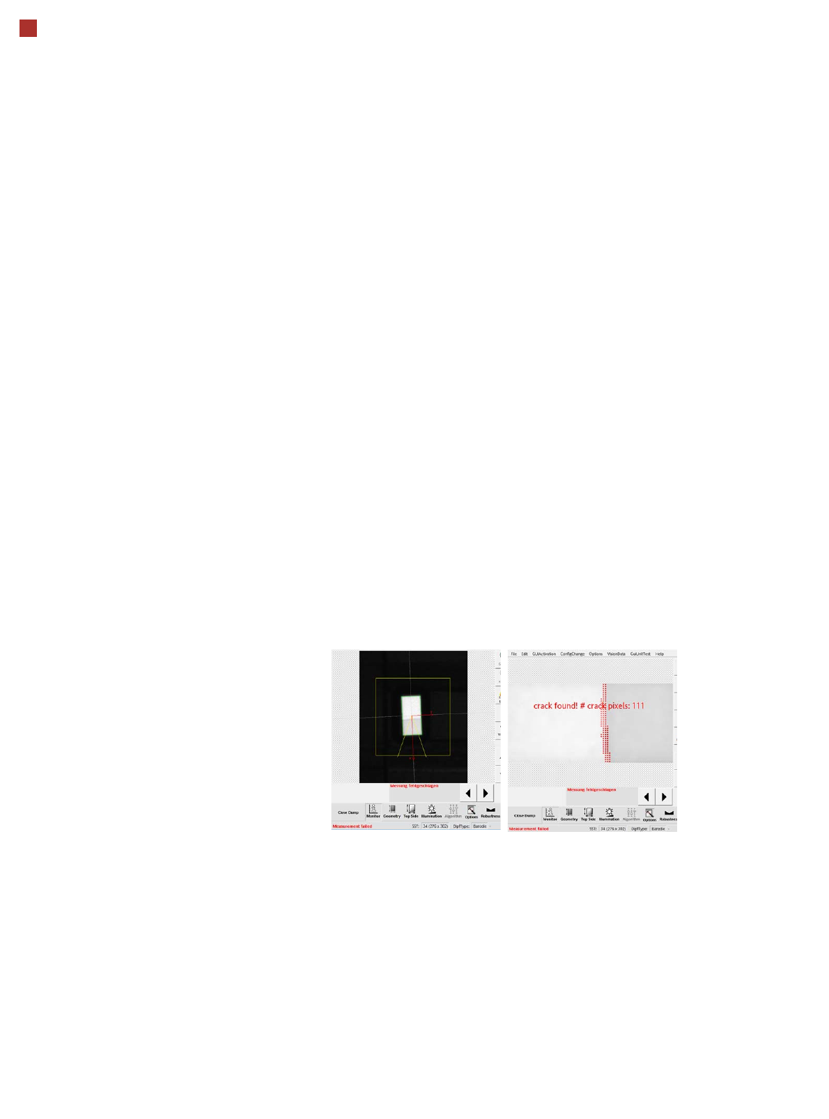
Chipping Inspection
The Chipping Inspection is
used to detect damage
(chips etc.) to semiconductor
parts.