SIPLACE TX V2 micron 设备性能参数_DMS.pdf - 第28页
28 OSC package The licensed OSC pack age contains functions for auto- matic determination of the optimum ac celeration. The license is activate d via SIPLACE PRO. For detailed information, refer to the OSC package user g…

27
SIPLACE Vision
Barcode types
Technical data
1D barcodes
QR codes
Code types Code 39
Code 93
Code 128
EAN-8 (AddOn 2, AddOn 5), EAN-13 (AddOn 2, AddOn 5)
Interleaved 2 of 5
Minimum width of bar 5 pixels
If the quality of the mark is sufficient, the width can be reduced down to 3
pixels.
Minimum height of symbol 5% of length of whole symbol.
Symbol angle All symbol angles will be accepted.
Inverse symbols Light bars on a dark background will be accepted.
Mirrored symbols Mirrored symbols will be accepted.
(this corresponds to a rotation of 180 degrees for 1D codes)
Region of Interest (ROI) The area on the PCB, in which the barcode is searched for (ROI), should
not exceed the following values:
ROI (direction of reading)
≤ 3 * symbol width
ROI (vertical to direction of reading)
≤ 10 * symbol width
Code type QR code in accordance with ISO/IEC 18004 model 2.
Station software version 711.0 or higher required
No. rows/columns All versions still defined in the standard (i.e. number of rows/columns) are
accepted.
Minimum dot size 5 pixels.
Symbol angle All symbol angles will be accepted.
Inverse symbols Inverse symbols (light modules on a dark background) will be accepted.
Mirrored symbols Mirrored symbols will be accepted.
Ratio of column width to row
height
1/2
≤ (column width) / (row height) ≤ 2
Region of Interest (ROI) The area in which the barcode is searched for (ROI) should not exceed the
following values:
Width of ROI
≤ 6 * width of barcode symbol
Height of ROI
≤ 6 * Height of barcode symbol
28
OSC package
The licensed OSC package
contains functions for auto-
matic determination of the
optimum acceleration.
The license is activated via
SIPLACE PRO.
For detailed information,
refer to the OSC package
user guide, item number
[00198374-xx].
The following functions are
contained in the OSC pack-
age for the SIPLACE TX m:
Automatic calculation of
optimum acceleration
This function enables the
user to automatically calcu-
late the optimum accelera-
tion of individual axes for a
component at the station.
The acceleration values
found can then be checked in
an additional test run and
sent back to the program-
ming system if successful.
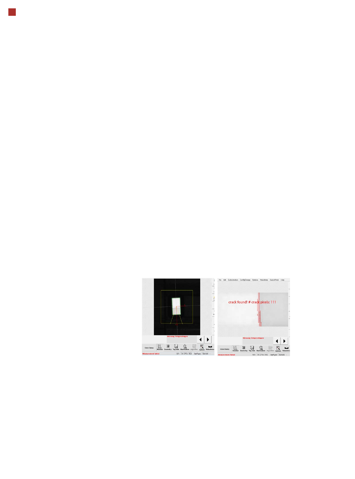
Chipping Inspection
The Chipping Inspection is
used to detect damage
(chips etc.) to semiconductor
parts.
29
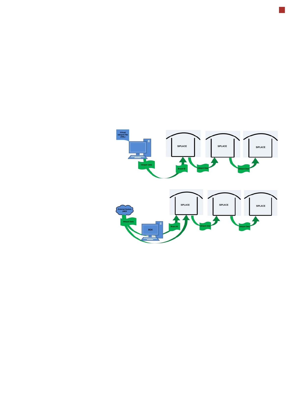
Virtual Inkspot Handler (VIH)
The virtual inkspot handler
(VIH) allows you to scan in
inkspots from an external
system.
This option can be used for
external systems to define
which panels are to be
produced and which to be
omitted. A panel is a specific
part of a printed circuit
board. This concept is much
more flexible than the
physical inkspot concept.
It can be integrated into the
ongoing production process,
if external systems
individually decide whether
each panel it is in a good or
bad state and whether
additional processing steps
are to be omitted or not.
The PCBs are typically
measured by the external
system and the information
about which panels are good
or bad is then available.
The use of this information
via VIH offers the benefit that
no physical inkspots need to
be read by the PCB camera.
This improves performance,
particularly for PCBs with a
large number of panels.
This option can also be used
if the panels do not have
room for a physical inkspot.
Workflow VIH with XML file
Workflow VIH with MES and BoardGateKeeper (BGK)
Process Data Interfaces (PDI)
The process data interface (PDI), which can be addressed via
the OIB interface, enables you to access not only the trace-
ability data of the components placed but also various process
parameters for the component placement. The PDI makes
over 40 process attributes per placement position available,
such as:
• Pickup (actual pick position, pickup location ID)
• Dipping (result, timestamp)
• Vision measuring (result plus camera ID)
• Placement (actual place position, ref. desig., vacuum val-
ues)
The data packages contain the data for each PCB and stop-
per position.
Each individual data package contains a maximum of 200
placement positions.