SIPLACE TX V2 micron 设备性能参数_DMS.pdf - 第35页
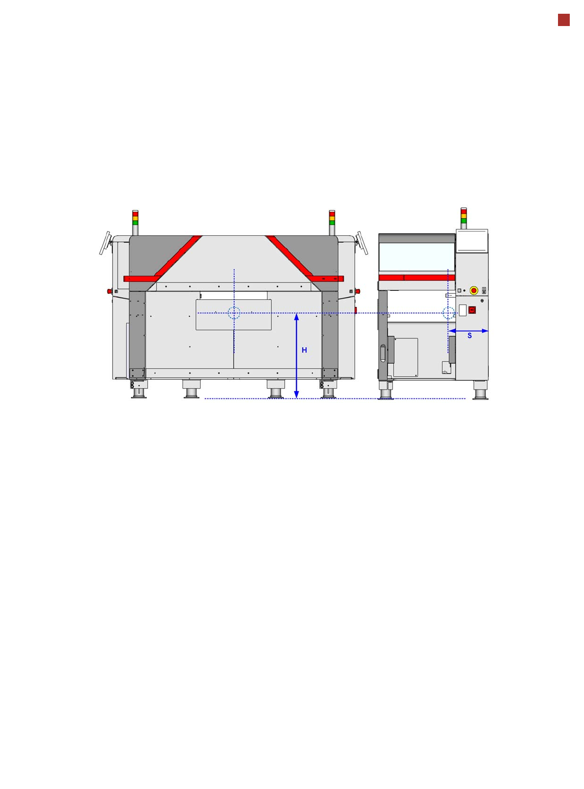
35 Technical data Machine dimensions Machine center of gravity Center of gravity S = 420 mm / H = 750 mm
34
Technical data
Dimensions and setup conditions
Length
a
Without conveyor extension and with hand guard
With input conveyor extension
b
With output conveyor extension
With input and output conveyor extension)
a) Measured at the outer contour of the machine protection.
b) Only at the first machine in the line.
1000 mm
1260 mm
1604 mm
1864 mm
Width
Outer contour of machine protection (both tables "inside")
With monitor
Outer contour of machine protection (table location 1 "outside")
With monitor
2232 mm
2420 mm
2347 mm
2441mm
Height of machine (for PCB conveyor height 950 mm)
Machine protection closed
With 2-color indicator lamp
With 3-color indicator lamp
Without indicator lamp (height of packaging)
With folded-up short protective cover 45 degrees position
With folded-up short protective cover 60 degrees position
With folded-up short protective cover 45 degrees position
With folded-up short protective cover 60 degrees position
1500 mm
1690 mm
1735 mm
1500 mm
1960 mm
2070 mm
2050 mm
2175 mm
Machine ground clearance for TX m
(for PCB conveyor height 900 mm)
(for PCB conveyor height 930 mm)
(for PCB conveyor height 950 mm)
120 mm ± 13 mm
150 mm ± 13 mm
170 mm ± 13 mm
Weight
SIPLACE TX m (without feeder modules)
SIPLACE TX m (fully equipped with feeder modules)
2050 kg
2150 kg
Location
c
With tables in outer position
c) Measured at the outer contour of the machine protection and without conveyor extension.
2.23 m²
2.33 m²
Even floor surface load (without feeder module)
Even floor surface load(with feeder module)
Characteristic surface load
6.46 kN/m²
6.79 kN/m²
7.70 kN/m²
Number of machine feet 4
Max. noise emissions 75 dB (A)
Atmospheric humidity 30% to 75% (no higher than 45%
on average to prevent any possi-
bility of condensation on the
machine)
35
Technical data
Machine dimensions
Machine center of gravity
Center of gravity S = 420 mm / H = 750 mm
36
Technical data
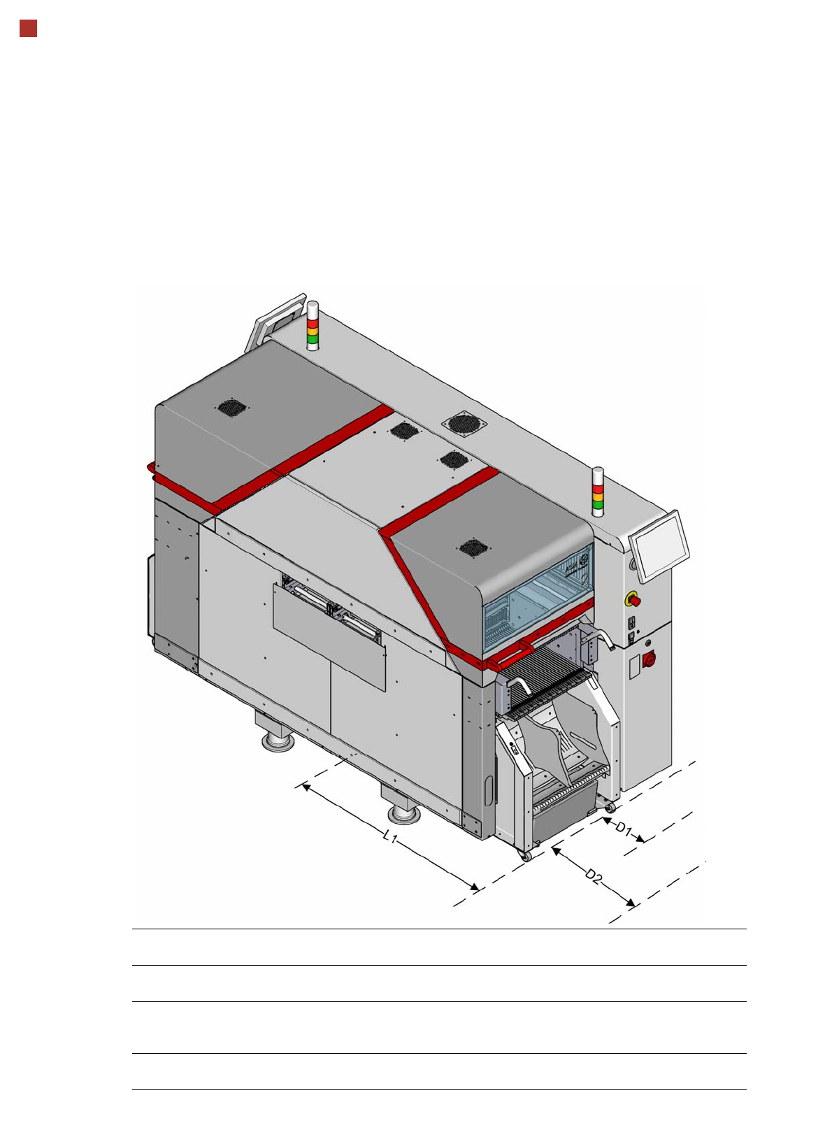
Maneuvering distances for component trolleys
Pos. Description Location
(outside)
Location (inside)
D1 Minimum required maneuvering distance for moving
component trolley out.
750 mm 650 mm
D2 Recommended maneuvering distance for moving com-
ponent trolley out.Distance to adjacent machine/line or
the building wall.
990 mm 990 mm
L1 Distance from machine center to outer edge of compo-
nent trolley
1222 mm 1102 mm