YG12F_Ope_E.pdf - 第49页
1-15 1 Part names and functions 5. Conveyor unit and component recognition system The conveyor unit used to clamp a board in mounting position is described below . 4 5 2 1 6 Con veyor unit 3 23114-M7-00 1. Main stopper W…
1-14
1
Part names and functions
n
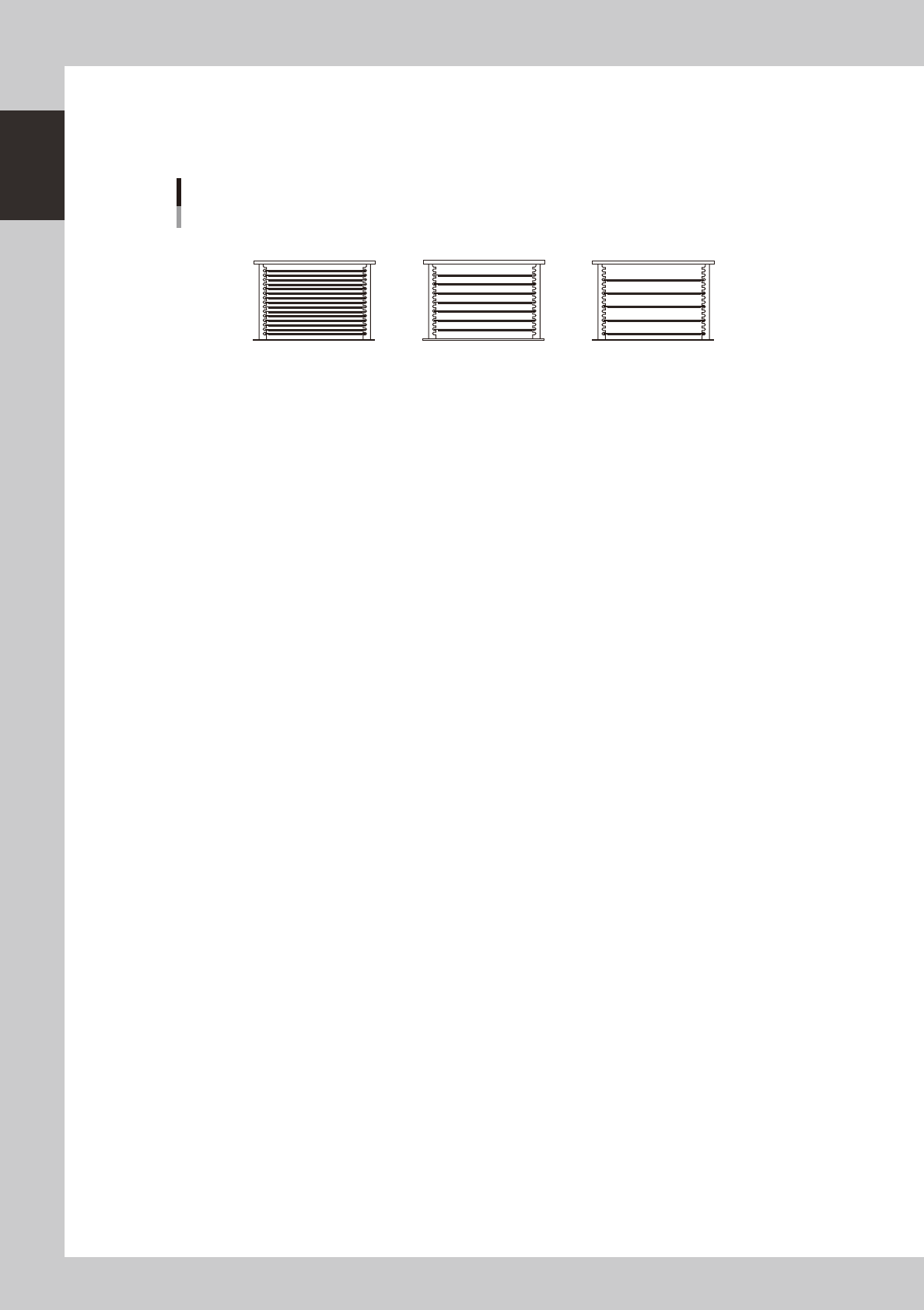
Pallet storage examples
The ATS15 holds up to 15 pallets (at a pallet storage pitch of 12.5 mm).
When tall components are to be used, change "Pallet Pitch Z" in the parts information to "Double Pitch" or "Triple Pitch"
depending on the thickness of the "component + component tray" loaded in the pallet.
Pallet storage examples
2
4
6
8
10
12
14
3
6
9
12
15
12.5mm pitch
(Pallet Pitch Z: Normal)
37.5mm pitch
(Pallet Pitch Z: Triple Pitch)
25mm pitch
(Pallet Pitch Z: Double Pitch)
Number of pallets stored in
magazine: 7
Number of pallets stored in
magazine: 15
Number of pallets stored in
magazine: 5
23113-M7-00
n
For details on how to use the tray changer
Please refer to the following manuals for details on how to use the tray changer.
How to operate and handle : YG series external supply equipment manual “ATS15”
How to create tray data : YG series programming manual
1-15
1
Part names and functions
5.
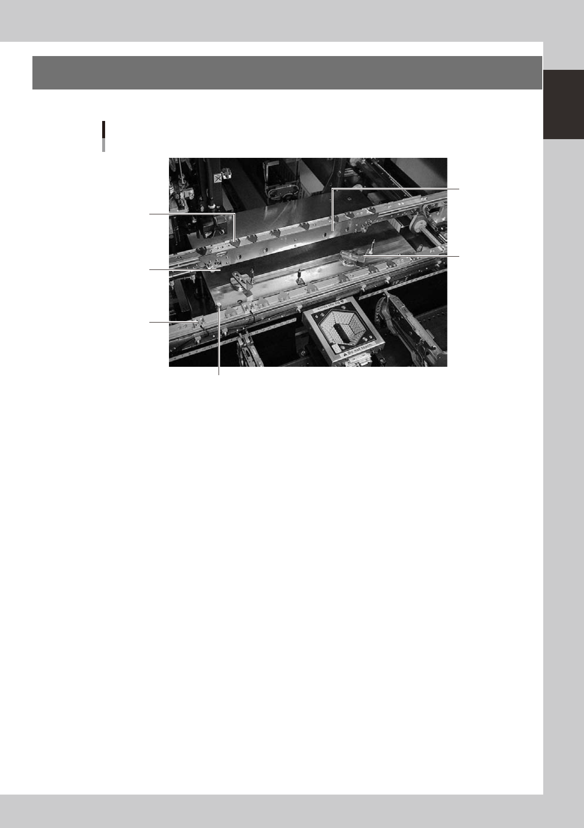
Conveyor unit and component recognition system
The conveyor unit used to clamp a board in mounting position is described below.
4
5
2
1
6
Conveyor unit
3
23114-M7-00
1. Main stopper
When a board is carried in on the conveyor, the main stopper halts travel of the board in the component mounting
position.
2. Push-up plate
The push-up plate clamps the board up against the conveyor rails, with the supporter pins attached by magnet on the
push-up plate.
3. Push-up pins
These pins are arranged on the push-up plate and secure the board by pushing it up from the bottom.
4. Board hold plate (movable)
These plates hold the edges of the board from above when the board is clamped in the mounting position.
5. Board edge clamp unit
This unit clamps the board by pushing its edges up against the board hold plates.
6. Board sensor
Board sensors are arranged at the conveyor entrance and exit, "standby position", "board clamp position", etc.
1-16
1
Part names and functions
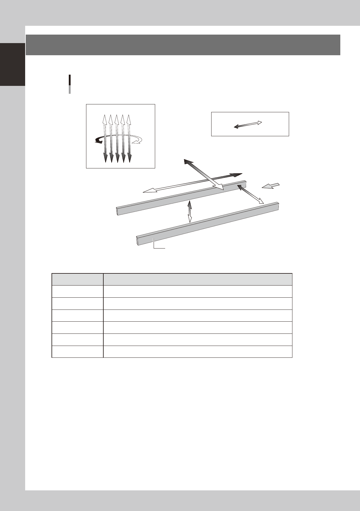
6. Axis configuration
The machine axis configuration and operation are shown in the drawing and table below.
Y axis
X axis
W axis
PU axis
Plus direction
Minus direction
Board
Conveyor rail
R axis
Head
Axis configuration
Z1Z2Z3Z4Z5
23115-M7-00
n
Function of each axis
Axis Function
X Moves the head assembly in parallel with the board flow on the conveyor.
Y Moves the head assembly perpendicular to the board flow on the conveyor.
Z1 to Z5 Controls the height of each head.
R Rotates the nozzle shafts of each head.
W Changes the conveyor width.
PU Moves the push-up plate vertically.