YG12F_Ope_E.pdf - 第70页
2-12 2 asic operation 2.3 Unit screen T his section describes the manual operation buttons on the Unit screen. n Manual conveyor operation 1 Con veyor manual b uttons 3 2 4 5 6 7 8 9 10 11 24204-M7-00 1. Convey In Move…
2-11
2
asic operation
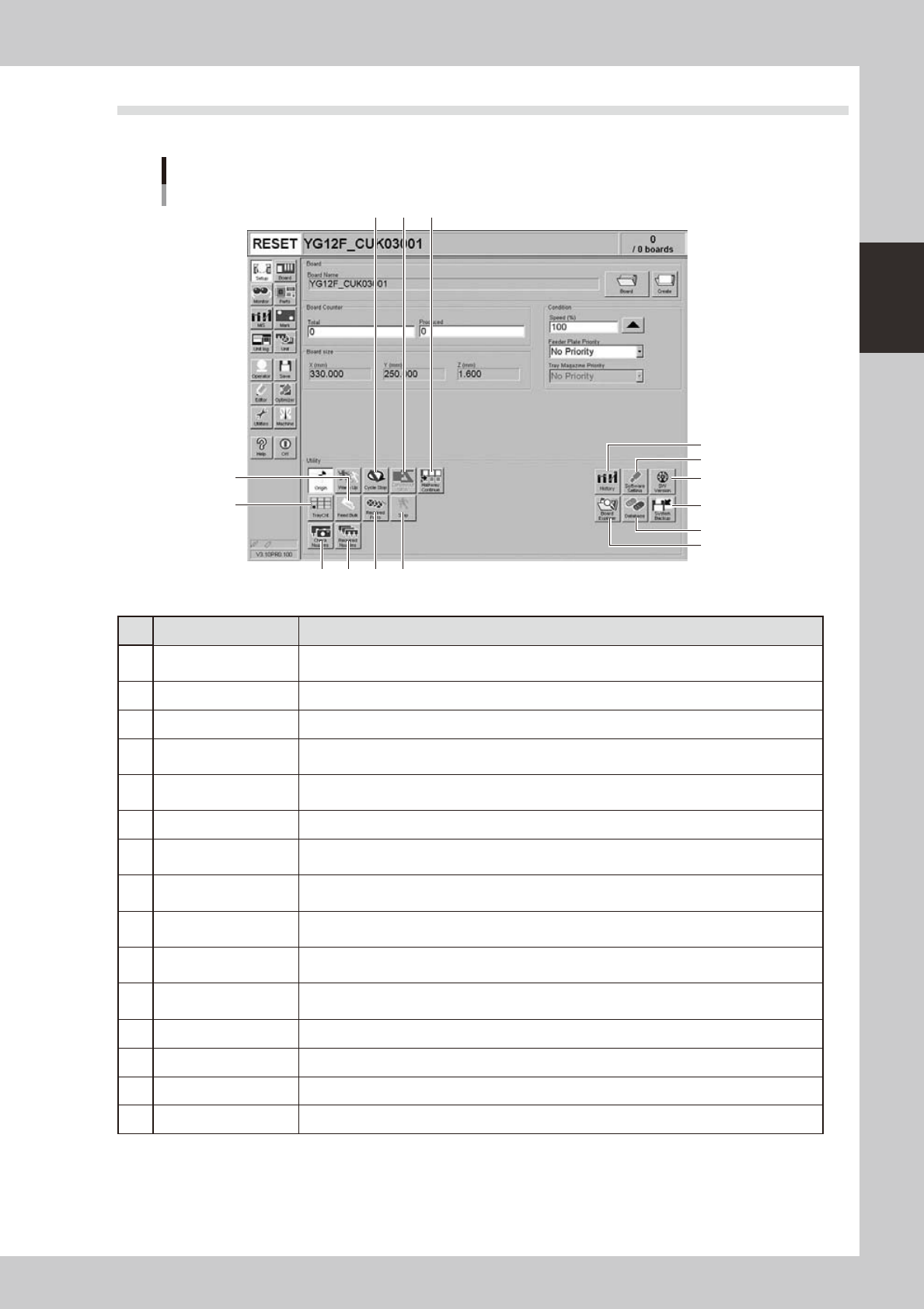
2.2 Setup screen
This section describes the operation buttons displayed on the Setup screen.
Setup screen
1
2
3
4
5
6
7 8 9
10111213
14
15
24203-M7-00
Button name Function
1 History
Saves production history data, and saves or clear any desired items of "MIS" and "Unit log"
records. Also use this button when removing a storage medium from the machine.
2 Software Setting Sets machine screen display items, adds or deletes operators, and sets passwords.
3 Version Shows version information on application software and system.
4 System Backup
Makes a backup of machine coordinates, accuracy information, option device information and
standard coordinates necessary for machine operation or restores the data using the backup.
5 Database
Makes a backup of parts and mark database necessary for board production or restores the data
using the backup. Also sets the database locations.
6 Board Explorer Moves, backs up, restores or copies board data.
7 Cycle Stop
Stops machine operation just after mounting components on the current board, for example, to
check the mounted results or to prevent the board from flowing to the downstream machine.
8 Convey-out Stop
Stops machine operation after mounting components on all boards on the conveyor and
transferring them to the downstream machine.
9 Halfway Continue
After stopping the machine for some reason during component mounting and resetting the data,
pressing this button loads that data to resume component mounting from the next mount point.
10 Step
Temporarily stops the machine at a specific position, for example, during initial component
mounting, test mounting, or trouble analysis.
11 Required Parts
Displays the component types and feeder positions that are set up for the production to be
started.
12 Required Nozzles Displays a list of nozzles to be used.
13 Check Nozzles Not currently used.
14 Tray Cnt Displays the number of tray components that have been used.
15 Feed Bulk Not currently used.
2-12
2
asic operation
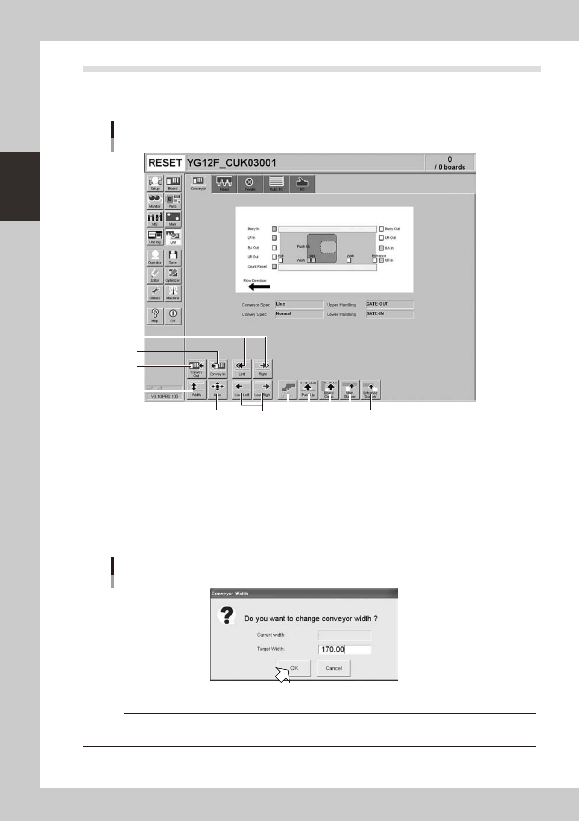
2.3 Unit screen
This section describes the manual operation buttons on the Unit screen.
n
Manual conveyor operation
1
Conveyor manual buttons
3
2
4
5
6
7 8 9 10 11
24204-M7-00
1. Convey In
Moves the board from the conveyor entrance or standby position to the clamp position and clamps it.
2. Convey Out
Unclamps the board and moves it to the exit stopper position.
3. [Width] button
Use this button to adjust the conveyor width to match the width of boards to be produced.
Pressing this button displays the "Conveyor Width" dialog box. Check the conveyor width and press the [OK] button. The
conveyor rail automatically changes to the specified width.
"Conveyor Width" dialog box
24205-M7-00
c
conveyor units.
2-13
2
asic operation
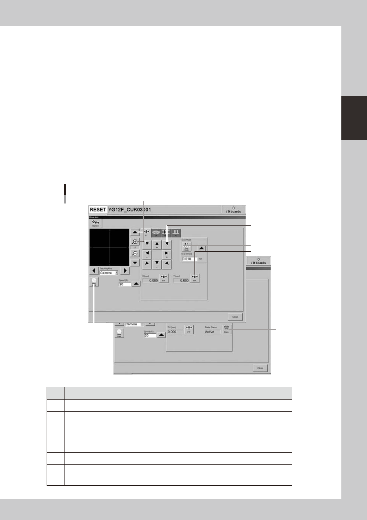
4. [Axis] button
Pressing this button opens the "Move Axis" screen as shown below. You can manually move each axis at a specified step
stroke with the arrow buttons or to a specified position with the [PTP] button.
5. [Left] button, [Right] button
Rotates the conveyor motor in the left or right direction at high speeds.
6. [Low Left] button, [Low Right] button
Rotates the conveyor motor in the left or right direction at low speeds.
7. [Exit Stopper] button
Raises or lowers the exit stopper that stops a board at the conveyor exit.
8. [Push Up] button
Pressing this button opens a dialog box for entering board thickness. Check or enter the board thickness to clamp the
board by pushing it up from the bottom (underside).
9. [Board Clamp] button
Clamps the board by pushing up its edges from the bottom (underside).
10. [Main Stopper] button
Raises or lowers the main stopper that stops a board in the clamp position on the conveyor.
11. [Entrance Stopper] button
Raises or lowers the entrance stopper that stops a board at the standby position.
"Move Axis" screen
1
2
3
4
5
6
24206-M7-00
Button name Function
1 Zoom in/out (+, -) Zooms in or out the image. (16 times to 1/16 times)
2 Mark Light Allows changing mark lighting manually. Using this button does not affect data.
3 PTP
Displays the "PTP" dialog box that allows directly specifying the position where
you want to move the selected axis.
4 Step Mode
When this button is pushed in, the selected axis can be moved in "step mode
(inching mode)" with the arrow buttons at a specified step stroke (inching stroke).
5 Arrow Use these buttons to move the selected axis in the desired direction.
6 Brake
Use this button when you want to release the brake during emergency stop.
(W-axis and PU axis only)
The brake is automatically released when the servo is turned on.