Specification_SIPLACE_S23HM_eng.pdf - 第29页
28 Description Productivity c an be further en- hanced by knowing exactly the current condit ion and utilization rate of the system, about idle times which occur and their causes. This inf ormation is sup- plied by ”prod…

27
Description
A single placement program on the
line computer is sufficient for all of
the SIPLACE machines in a pro-
duction line. It contains the neces-
sary data for population of a spe-
cific PCB type - from the
dimensions of the PCB over the
placement positions of the com-
ponents to the complete compo-
nent and GF library. The program
can be created manually by means
of editors in the editors in the
SIPLACE line computer or - simple
and time-saving - can be generated
automatically from the CAD data of
the PCB. The converted data im-
ported with the aid of a CAD post-
processor can be transferred into
the data pool of the SIPLACE line
computer via a standard LAN. The
placement programs are then
transferred from the HOST com-
puter directly into the line com-
puter’s master data.
The CAD postprocessor can be
variable adjusted insofar as the se-
quence of the data and the format
is concerned. The data to be con-
verted must meet the following
preconditions:
ASCII data
Table-oriented: on line per
placement position
Separators can be variably ad-
justed but must be identical for
all fields
Minimum information content:
component name, X-, Y-, angle
position.
The central filing of the line com-
puter (master) data enables an
automatic link to higher-level com-
puter systems. Revisions there-
fore automatically affect all con-
nected, appropriately configured
lines. It is possible to switch be-
tween local and central data man-
agement at any time.
Placement programs of earlier
SIEMENS SMD placement ma-
chines which could be run on an
SP-120/HS-180 line or on MS-1xx
machines (BP and BM files) can be
transferred using a conversion
program integrated into the
SIPLACE line computer. It is also
possible to continue to use post-
processors for SP/HS and MS data
formats. The data are converted
into the SIPLACE format and
stored in the line computer. There
they must be supplemented by
additional required information
such as PCB dimensions, configu-
rations of subpanels in the cluster
and set-ups.
An additional computer which has
the same hardware and software
configuration as the line computer
can be utilized as an external pro-
gramming station. Even if physi-
cally separate from the production
equipment, it manage placement
programs and other data for a
number of lines link them via LAN
to the line computers in produc-
tion.
The file format <set-upname>.rt,
in which set-up data in simple form
can be generated, makes it possi-
ble to import set-ups which were
programmed on systems of the
customer or third-party manufac-
turers. It facilitates the program-
ming on external systems and the
use of higher-level production con-
trols. This file is also kept in table-
oriented ASCII form and can there-
fore be created very easily.
The aim of SIPLACE set-up optimi-
zation is to reduce placement
times and non-productive machine
times. In this process, attention
dedicated to the optimal balancing
of the entire line, not just the
minimum placement time of each
individual machine. The nozzle al-
location of the placement heads is
adapted to the individual PCB. To
reduce travel distances, the opti-
mal erection location for the feeder
and the best sequence of place-
ment are calculated. As long as the
component feeding capacity of a
SIPLACE line permits it, the set-up
optimization can combine a num-
ber of products in a single set-up.
An optional add-on is the optimiza-
tion of the sequence of placement
which optimally combines a rela-
tively large number of products in
a number of set-ups. Attention is
directed to the changeover and
set-up times, not just to the short-
est possible throughput times and
optimal balancing of the entire line.
SIPLACE Software Architecture:
Creation of Placement Programs
Generation of the placement program from CAD data of the PCB
Data conversion Configurable postprocessor of the line computer
or external postprocessor of the CAD system
manufacturer or another manufacturer
Data transfer Standard LAN
(Ethernet TCP/IP and FTP or NFS)
or diskettes (MS-DOS; UNIX)
28
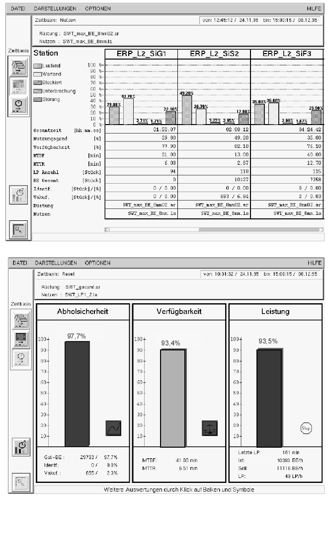
Description
Productivity can be further en-
hanced by knowing exactly the
current condition and utilization
rate of the system, about idle
times which occur and their
causes. This information is sup-
plied by ”production and machine
data acquisition systems”
(PDA/MDA). The SIPLACE Ma-
chine Data Management System
collects all relevant data for the line
and individual stations and pres-
ents it graphically. The data in-
cludes analyses of availability, pick-
up error rates, placement speed,
MTBF and MTTR as well as for
track error display with component
item number and package form
number. This speedy, clear view of
the operating behavior provides
starting points for possible im-
provements.
SIPLACE Software Architecture:
Machine Data Management System
Screen Shots
29
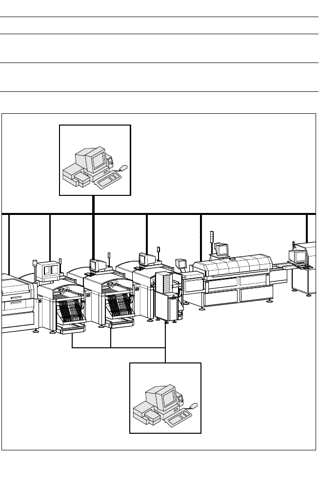
Configuration of a Production Line with GEM Computer
Description
The function of Semiconductor
Equipment Communication Stan-
dard (SECS) II is to uniformly de-
fine communication interfaces of
production equipment made by
different manufacturers. It was fur-
ther developed into the GEM
Standard (General Equipment
Model) which is also suitable for
SMT production equipment. In this
case, an external user-specific
production computer (host) is con-
nected via LAN to a GEM com-
puter integrated into the machine
control. The interface is used by
host systems created by the user
or applications software from third-
party manufacturers.
The SECS II / GEM communication
protocol supports central control,
process control and their data
management of complete produc-
tion lines on the line computer.
Using Statistical Process Control
(SPC), for example, it is possible to
implement preventive mainte-
nance which prevents or greatly
reduces production down times.
SIPLACE Software Architecture:
Data Interface SECS II / GEM (Option)
Factory LAN GEM
Functions
Identification of the equipment
Real Time Access-
ing
Product data, error messages, machine states,
measurement results
Saving Information, connections
(connection set-up, resynchronization
SIPLACE LAN
Line Computer
HOST
GEM
GEM
GEM
GEM