Specification_SIPLACE_S23HM_eng.pdf - 第7页
6 Description One nozzle changer can be i n- stalled for the 12-nozzle revolver head on each the left and right of the PCB conveyor with no loss of feeder locations. The revolver head changes the placement quickly and re…
5
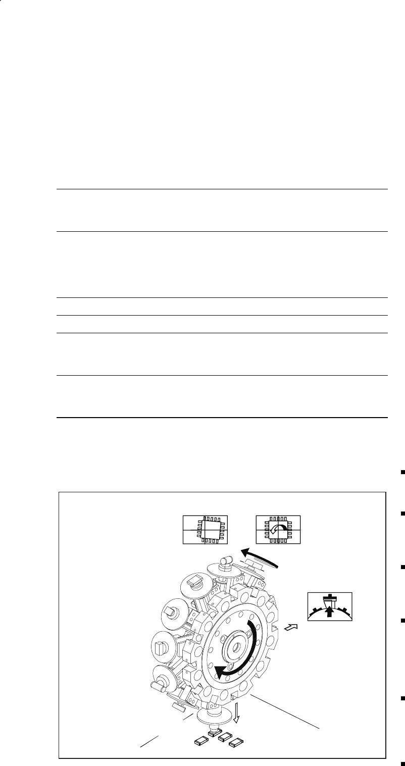
Revolver Head Functions
Component Pick-Up/
Placement
Segment
Removal
Point
Turning to
the Placement
Position
Component
Vision
Description
The 12-nozzle revolver head oper-
ates on the Collect & Place princi-
ple. In contrast to classic shooters,
the 12 vacuum nozzles of the
SIPLACE revolver heads rotate
around a horizontal axis. This does
not just save space: Due to the
small diameter compared to
shooters, the centrifugal forces
which develop are significantly
lower. The results are high-speed,
reliable placement and the same
cycle time for all components.
Components are picked up and
placed gently and reliably with the
aid of vacuum or blast air. A num-
ber of vacuum tests indicate
whether the component has been
picked up and placed accurately.
Various control and self-learning
functions further enhance the de-
pendability of the system:
The optical recognition of feeder
positions furnishes the exact
position of the feeder table.
A camera on the revolver head
(component vision module) de-
termines the exact position of
each component on the nozzle.
Offsets in position are corrected
prior to placement and taken
into consideration during further
component pick-up.
In addition, the package form is
also checked. If the actual geo-
metric dimensions of the com-
ponent do not correspond to
those programmed, the place-
ment is not carried out.
Irregularities in the PCB surface
are balanced out due to the
sensor-stop operation while the
nozzle is being lowered and they
are also ”learned”.
Components recognized as be-
ing faulty are rejected by blast
air and are automatically added
during a repair run.
Placement Heads:
12-Nozzle Revolver Head for High Speed
Technical Data
Component spectrum* 0402 (0201**) to 18.7 x 18.7 mm,
incl. BGA, µBGA, Flip Chip, QFP,
TSOP, PLCC, SO to SO32, DRAM
Max. height*
min. lead pitch
min. dimensions
max. dimensions*
max. weight*
6 mm
0.5 mm
0.5 x 1.0 mm
18.7 x 18.7 mm
2 g
Stroke of Z-axis max. 16 mm
Programmable placement force 2.4 to 5.0 N
Angle accuracy
± 0.525° / 3 σ
± 0.70° / 4 σ
± 1.05° / 6 σ
Placement accuracy
± 67.5 µm/ 3 σ
± 90 µm/ 4 σ
± 135 µm/ 6 σ
* A uniformly reliable, speedy and accurate placement is guaranteed up to these limit values. Above
and beyond this, components can be placed if they satisfy specific basic conditions (For other
components please contact Siemens).
** 12-nozzle revolver head is capable of handling 0201 (Please contact Siemens).
6
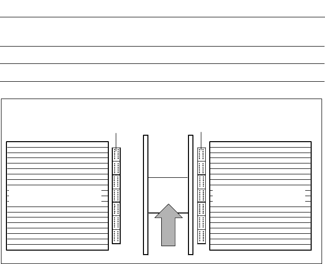
Description
One nozzle changer can be in-
stalled for the 12-nozzle revolver
head on each the left and right of
the PCB conveyor with no loss of
feeder locations. The revolver head
changes the placement quickly and
reliably for the nozzle configuration
required for a particular job. Dam-
aged or faulty nozzles can be ex-
changed via menu function.
Placement Heads:
Nozzle Changer for 12-Nozzle Revolver Head (Option)
Nozzle Changer for
12-Nozzle Revolver Head
for 7 Ma
g
azines for 12 Nozzles (O
p
tion)
Technical Data
Type of nozzle All standard nozzles of nozzle series 9xx
(special nozzles have to be checked individually)
Capacity 7 magazines for 12 nozzles
Nozzle changing times About 2 s per nozzles
Component Feeder
Component FeederPCB
7
PCB Transport
Direction
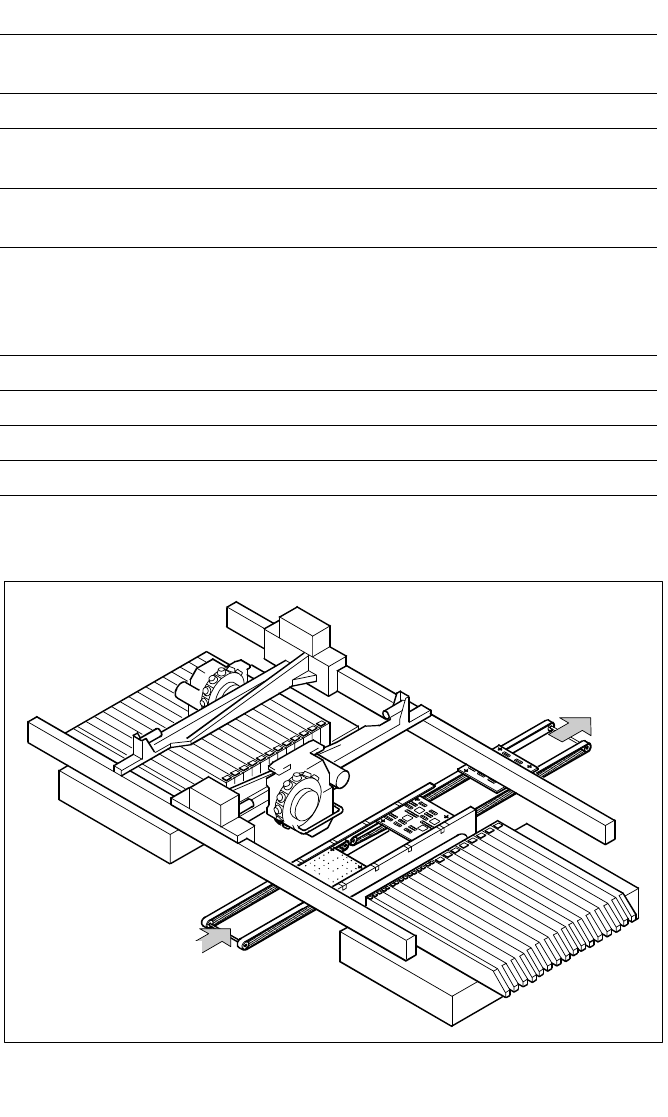
Description
On SIPLACE S-23 HM placement
machines the in-line conveyor sys-
tem ensures a speedy adjustment
to new PCB widths. The changeo-
ver is made either at the station via
menu function or from the line
computer via the automatic width
adjustment. Ceramic substrates
are also transported or fixed in
place by means of the optional ce-
ramic substrate centering feature.
As standard the SIPLACE place-
ment system are available with a
single conveyor system.
PCB Conveyor:
Single Conveyor
PCB Conveyor
Technical Data
PCB dimensions 50 x 50 mm to 460 x 460 mm
(optional 460 x 508 mm)
PCB thickness 0.5 to 4.5 mm
Max. PCB warp Top: 4.5 mm - PCB thickness
Bottom: 0.5 mm + PCB thickness
PCB underside clearance Standard: 25 mm,
Option: max. 40 mm
PCB conveyor height
830 ± 15 mm (Standard)
900 ± 15 mm (Option)
930 ± 15 mm (Option)
950 ± 15 mm (Option) SMEMA
Fixed conveyor edge On right (standard); on left (option)
Type of interface Siemens (standard); SMEMA (option)
Component-free handling edge 3 mm
PCB changing time 2.5 s