Vakuumtooling an HS60.pdf - 第33页
Special design 2 Assembly in structions Special design Vacuum tooling SIPLACE HS-60 10/2006 Edition 33 2 Assembly instructions S pecial design V acuum tooling SIPLACE HS-60 2.1 Requirement s 2.2 Activation of the option …
1 Montageanleitung SOKO Vakuum-Tooling SIPLACE HS-60 SOKO
Ausgabe 10/2006
32
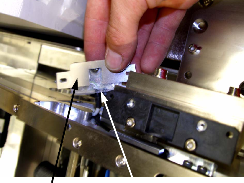
: Legen Sie die Abdeckung wie auf dem unteren Bild zusehen auf die Laserlichtschranke und
schrauben Sie die Lichtschranke wieder mit den beiden Schrauben fest.
1
1
1
1
Laserlichtschranke
Abdeckung

Special design 2 Assembly instructions Special design Vacuum tooling SIPLACE HS-60
10/2006 Edition
33
2 Assembly instructions
Special design Vacuum tooling
SIPLACE HS-60
2.1 Requirements
2.2 Activation of the option
The option is activated if plug X34 and X35 are plugged and the vacuum tooling is activated in the
conveyor firmware. 2
The switch in the centre of the conveyer enables to deactivate and activate the option. 2
A reboot of the machine is necessary in this case. 2
2.3 Restrictions
– The vacuum tooling is only designed for the provided test boards. If another product should be
produced on the machine or a service tool should be used, the machine has to be refitted to
the standard.
– After changes in the conveyor firmware the option possibly has to be activated again.
– The automatic width adjustment should be deactivated at the station and at the SIPLACE Pro
computer, to avoid crashes between the conveyor and the tooling.
– To avoid clamping of the PCB, spacers have to be fitted below the conveyor.
– After an air pressure drop (hint in GUI: Compressed air failure for too long) the fixing of the PCB
on the vacuum plate should be checked. Process reliability cannot be guaranteed after a drop
in the compressed air pressure.
– If additional options are integrated in the conveyor, further restrictions have to be made or the
other options have to be removed.
– The option must not be activated or deactivated during placement process.
2
2
Hardware:
SIPLACE HS-60
Software:
505.xx or higher

2 Assembly instructions Special design Vacuum tooling SIPLACE HS-60 Special design
10/2006 Edition
34
2.4 Possible variations
– The shape and size of the vacuum tooling might varies for different PCB’s.
– For dual conveyor machines, the installation for the second conveyor is identical with the first
conveyor installation. The only changing is that the vacuum devices have to be fitted sideways
on the machine base and not on the lifting table.
2.5 Scope of delivery
2
For dual conveyor the following material has to be delivered twice. 2
2
2
Independent from the conveyor type 2
2.6 Necessary tools
– Set of allen keys
– Set of screw drivers
–Wire cutter
– Hose cutter
– Cable ties
– Clue pads for cable ties
2
2x
Option lifting tables (SC 00367190-xx/DC 00367189-xx)
2x
Vacuum toolings with vacuum devices
8x
Spacer for lifting limitation 3,2mm (03013648-xx)
2x
Screws M4x16mm
1x
PUN 8 – hose, approx. 5m
1x
PUN 10 – hose, approx. 2m
1x
New cover plate for the maintenance unit
1x
Maintenance unit (00176066-xx)
1x
Assembly instruction