Vakuumtooling an HS60.pdf - 第53页
Special design 2 Assembly in structions Special design Vacuum tooling SIPLACE HS-60 10/2006 Edition 53 2.8.5.2 Pneumatic diagram 2
2 Assembly instructions Special design Vacuum tooling SIPLACE HS-60 Special design
10/2006 Edition
52
2
2
2
2
2
2
2
2
2
2
2
2
2
2
Vacuum tooling
Special design 2 Assembly instructions Special design Vacuum tooling SIPLACE HS-60
10/2006 Edition
53
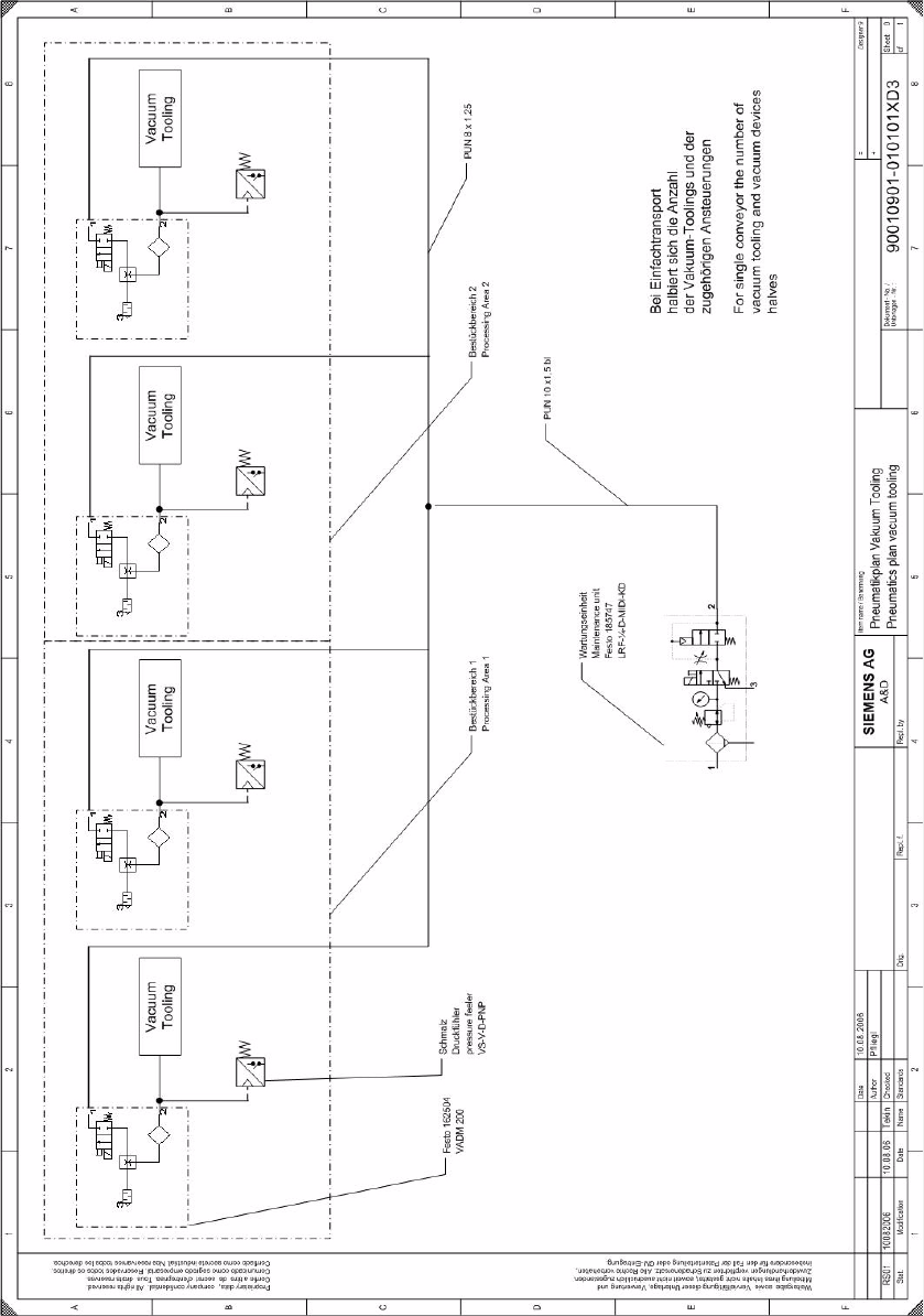
2.8.5.2 Pneumatic diagram
2
2 Assembly instructions Special design Vacuum tooling SIPLACE HS-60 Special design
10/2006 Edition
54
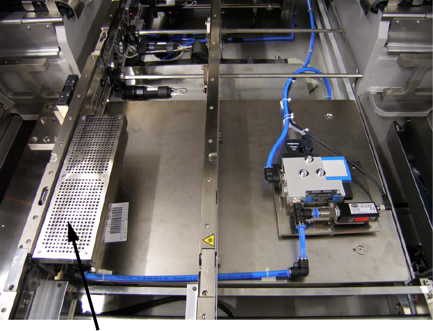
2.9 Installation of the spacers in the conveyor
The spacers avoid a clamping of the PCB. 2
2
2
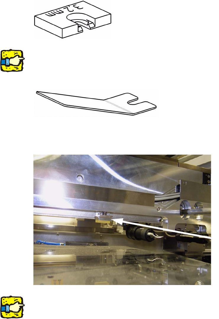
If the vacuum tooling will be removed, to produce other PCB’s, the 8 spacers also have to be re-
moved. 2
With the delivered tool the spacers are easy to fit. 2
2
: Push the tool under the spring and lift the spring gently.
: Push in one spacer per actuator. There are 4 spacers per processing area and conveyor line.
2
2
For removing the spacers follow the instructions in inverted direction. 2
2
Spacer