Vakuumtooling an HS60.pdf - 第39页
Special design 2 Assembly in structions Special design Vacuum tooling SIPLACE HS-60 10/2006 Edition 39 2.8.1.3 Programming of the sensor 2 Vakuum switch x Pressure switch VS-D Series BA 30.10.06.00010_E Status 12.2005 / …
2 Assembly instructions Special design Vacuum tooling SIPLACE HS-60 Special design
10/2006 Edition
38
The switch for activating and deactivating of the option has to be mounted on the top of the cover
plate of the conversion board. 2
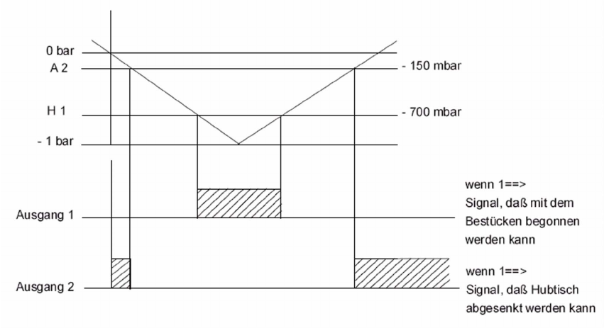
2.8.1.2 Working principle of the vacuum sensor
If the set vacuum level is not reached, the placement process cannot be started. 2
After finishing the placement process the vacuum has to relieve until the set level is reached, be-
fore the lifting table can drive down. 2
The thresholds are only checked directly after the lifting table drove up or drove down. 2
A drop in the vacuum pressure during the placement process will not be detected. 2
The set vacuum levels can vary depending on the size and layout of the PCB. 2
2
2
2
2
2
2
2
2
2
Special design 2 Assembly instructions Special design Vacuum tooling SIPLACE HS-60
10/2006 Edition
39
2.8.1.3 Programming of the sensor
2
Vakuum switch
x
Pressure switch
VS-D
Series
BA 30.10.06.00010_E
Status 12.2005 / Index 01
J. Schmalz GmbH, Aacher Straße 29, D-72293 Glatten
Tel 07443/2403-0, Fax -259
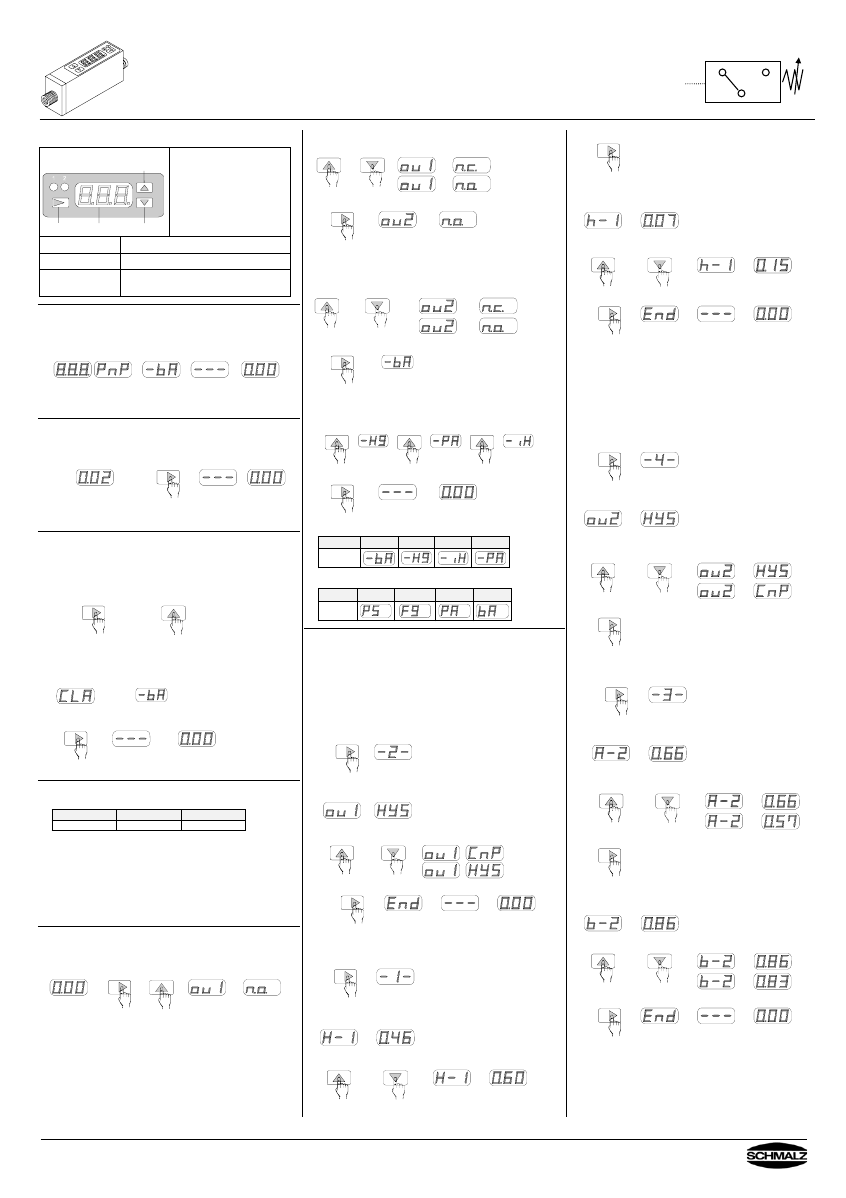
1. Front panel
LED Output 1
LED Output 2 Up
Mode Display Down
Display:
Preset values in setting mode.
Vacuum level in measurement
mode.
The minus sign is not
displayed when pressure
unit bar, inHg or mmHg is
selected (VS-V-D).
Mode
Button to select the different modes.
Up & Down Buttons to change settings.
LED Output 1
and Output 2
Switching indicator,
Output 1 = red, Output 2 = green.
2. Connecting power supply in normal operation
After connecting the power supply, in the display panel you can
see the presetted values.
When connecting the power supply do not push any key.
Type Selected
pressure unit
Display
Measured
pressure
3. Zero-point adjustment
Adjust the zero-point only when the vacuum/pressure line is not
connected. To adjust the zero-point, push the ”Mode“-key at
least 3 seconds.
Display Measured
p
atm
Hold for
min. 3 sec
Zero-point
adjusted
4. Clear All
If the switch was wrongly programmed, it can be set back in
to the factory settings.
All stored values are cleared. To accomplish this function,
disconnect the switch from the power supply. Whilst pushing the
”Mode“-key” and the ”Up“-key, connect the power supply again.
Push and hold both keys simultaneous
After connecting the power supply, the display shows “CLA“.
When you release the buttons, the presetted pressure unit is
displayed by “ -bA” resp. ”bA”.
When pushing the ”Mode“-key one time, the selected pressure
unit is confirmed and stored.
1x
To adjust an other pressure unit see paragraph 6.3
5. Factory settings
The switch is delivered with following factory settings
Unit Output 1 Output 2
bar HYS, N.O. HYS, N.O.
This setting can be changed (programmed).
The programming is described in the following paragraph.
A built-in EEPROM retains data for a period of min. 10 years.
The data are min. 10.000 times rewritable.
N.O = normally open, N.C. = normal closed,
HYS = operating mode „Hysteresis mode“
The initial settings of the operating mode is shown
in the table in paragraph 8.
6. Setting of output configuration (N.O. or N.C.) and
pressure unit (e.g. bar).
To adjust the output configuration and the pressure unit, push
and hold the ”Mode”-key, the push the “Up“-key.
hold
The display is alternating between “ou I“ and ”n.o.”
6.1 Selection N.O. or N.C. of output 1
To change the setting, push ”Up”- or “Down”-key.
Store the settings with the “Mode”-key
1x
Now the display switches to the selection of output 2,
the display changes from ”ou 2” to ”n.o.”
6.2 Selection N.O. or N.C. of output 2
To change the setting, push ”Up”- or “Down”-key.
Store the settings with the “Mode”-key.
1x
bar
Now the display switches to the selection of the pressure unit.
6.3 Adjust the pressure unit
To change the setting, push ”Up”- or “Down”-key.
mmHg
kPa inHg
Store the settings with the “Mode”-key.
1x
Possible pressure units for VS-V-D
Unit bar mmHg inHg kPa
Symbol
Possible pressure units for VS-P10-D
Unit psi kgf/cm² MPa bar
Symbol
7. Adjusting the operating mode
7.1 Adjusting output 1
Example: Switch VS-V-D, output 1 has the operating mode
“Hysteresis-mode“.
switching point: -0,6 bar
hysteresis: 0,15 bar
Further information to the modes see paragraph 8.
Adjusting the operating mode
To select output 1, push ”Mode”-key 2x.
2x
wait 2 sec
After 2 seconds, the display is alternating between “ou I“
and the preadjusted operating mode.
Push the ”Up”- or “Down”-key until “HYS“ for the desired
switching mode „Hysteresis-mode“ is displayed.
Store the settings with the “Mode”-key.
1x
Setting switching point and hysteresis
To select the switching point of output 1 push ”Mode”-key 1x.
1x
wait 2 sec
After 2 seconds, the display is alternating between “H-1“
and the preadjusted value.
To adjust the switching point, push the ”Up”- or “Down”-key
until the desired value is displayed.
Store the settings with the “Mode”-key.
1x
Now the display switches to the selection of the hysteresis.
The display is alternating between “h-1“ and the preadjusted
value.
To adjust the hysteresis, push the ”Up”- or “Down”-key until
the desired value is displayed.
Store the settings with the “Mode”-key
1x
7.2 Adjusting output 2
Example: Switch VS-V-D, output 2 has the operating mode
“Window comparator mode“
Switching points are between -0,57 bar and -0,83 bar
(lower margin A=-0,57, upper margin b = -0,83)
Further information to the modes see paragraph 8.
Adjusting the operating mode
To select output 2, push ”Mode”-key 4x
4x
wait 2 sec
After 2 seconds, the display is alternating between
“ou 2“ and “HYS“.
Push the ”Up”- or “Down”-key until “CnP“ for the desired
switching mode “Window Comparator Mode“ is
displayed.
Store the settings with the “Mode”-key.
1x
Adjusting the lower and the upper margin
To select the lower margin of output 2, push ”Mode”-key 3x
3x
wait 2 sec
After 2 seconds, The display is alternating between “A-2“
and the preadjusted value.
Push the ”Up”- or “Down”-key until the desired value is
displayed.
Store the settings with the “Mode”-key.
1x
Now the display switches to the adjustment of the upper
margin. The display is alternating between “b-2“ and the
preadjusted value.
To adjust the upper margin, push ”Up”- or “Down”-key.
Store the settings with the “Mode”-key.
1x
2 Assembly instructions Special design Vacuum tooling SIPLACE HS-60 Special design
10/2006 Edition
40
2
Vakuum switch
x
Pressure switch
VS-D
Series
BA 30.10.06.00010_E
Status 12.2005 / Index 01
J. Schmalz GmbH, Aacher Straße 29, D-72293 Glatten
Tel 07443/2403-0, Fax -259
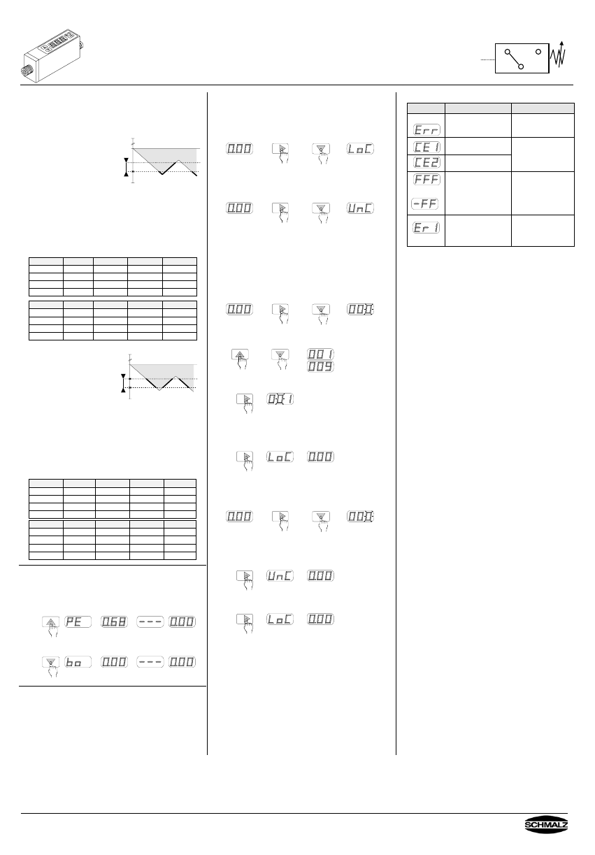
8. Operating modes of the outputs
The outputs can be operated in two different modes.
Each output can be adjusted independent of the other.
The modes are described in the following.
8.1 Hysteresis mode
Settings are switching point
H and hysteresis h.
Example: VS-V-D
H = -0.60 bar
h = 0.15 bar
N.O. (Normally Open)
0 bar
h
off on off
H
-1 bar
At 0 bar, the digital output is off.
When the vacuum level increases up to the switching point H,
the digital output switches on. As long as the vacuum is higher
than -0.45 bar ( = 0.6 bar - 0.15 bar), the digital output stays on.
When the vacuum decreases and passes -0.45 bar, the digital
output switches off.
For the configuration of N.C. (Normally Closed), the output
switches reverse ( off > H, on < H-h).
Factory setting: Output 1 & 2 in Hysteresis mode
VS-V-D mmHg inHg kPa bar
H - 1 345 13.6 -46 0.46
h - 1 50 2.0 -7 0.07
H - 2 595 23.4 -79 0.79
h - 2 50 2.0 -7 0.07
VS-P10-D psi kgf/cm² MPa bar
H – 1 67 4.75 0.46 4.6
h - 1 10 0,70 0.07 0.7
H - 2 115 8.2 0.79 7.9
h - 2 10 0.7 0.07 0.7
8.2 Window Comparator mode
Settings are lower margin A
and upper margin b.
Example: VS-V-D
A = -0.45 bar
b = -0.60 bar
N.O. (Normally Open)
0 bar
A
off
w
on on on
b
-1 bar off off
At 0 bar, the digital output is off.
When the vacuum level increases up to the lower margin A,
the digital output switches on. As long as the vacuum level is in
the ”window” between the lower margin A and the upper
margin b, the digital output stays on.
When the vacuum level becomes higher than the
upper margin b, the digital output switches off.
For the configuration of N.C. (Normally Closed), the output
switches reverse (A < off < b, A < on > b).
Factory setting: Output 1 & 2 in Window Comparator mode
VS-V-D mmHg inHg kPa bar
A - 1 195 7.6 -26 0.26
b- 1 400 15.6 -53 0.53
A - 2 495 19.4 -66 0.66
b - 2 645 25.4 -86 0.86
VS-P10-D psi kgf/cm² MPa bar
A - 1 38 2.7 0.26 2.6
b- 1 77 5.5 0.53 5.3
A - 2 96 6.85 0.66 6.6
b - 2 125 8.90 0.86 8.6
9. Display of Peak and Bottom values
The built-in memory stores in normal operation the peak value
and bottom value since the switch was connected to the power
supply.
These will be displayed as follow:
To display the peak valve, push the ”Up”-key
1x
Peak value
To display the bottom valve, push the ”Down”-key
1x
bottom value
10. Rotate display
If the mounting position is twisted (rotated on head), the display
can be rotated . When connecting the power supply, push and
hold the buttons “Up” and “Down”.
Note that the decimal point lights up now at the upper
margin of the display. The functions keys retain their
function , that means that the “Up“-key shows downwards
in twisted mounting position !
11. Locking the set values
11.1 Standard versions
Whilst pushing the ”Mode“-key, push the ”Down“-key. The
switch is locked, which means that the set values can’t be
changed. On the display appears ”LoC”, the switch is locked.
hold
When doing this once more, the switch gets unlocked and the
settings can be changed again.
On the display appears ”UnC”, the switch is unlocked.
hold
11.2 Version with PIN code (VS-...-C)
The lock prevents unauthorised persons changing the settings.
A 3-digit number combination (PIN code) guarantees that only
people who know the PIN code (set by the operator) can
change the settings.
Activating the lock:
To activate the lock, press and hold the “Mode” button, then
press the “Down” button.
hold
Press the “Up” or “Down” button to change the right digit.
The value for the right digit is saved when you press the “Mode”
button. The centre digit flashes.
1x
The centre digit can now be changed. Press the “Mode” button
again to change the left digit.
When the “Mode” button is pressed again, the PIN code entered
is saved. “LoC” appears on the display and the lock is activated.
1x
Deactivating the lock:
To deactivate the lock, press and hold the “Mode” button, then
press the “Down” button.
“000” appears on the display and the right digit flashes.
hold
The saved PIN code must be entered as described above for
locking. If the PIN code is correct, “UnC” is displayed and the
switch is unlocked.
1x
If the PIN code is incorrect, “LoC” is displayed and the switch
remains locked.
1x
If you forget the PIN code saved, the switch can be
unlocked in the SCHMALZ factory.
12. Error messages
Error Message Solution
Pressure during Zero-
point adjustment was
higher than ±3% F.S.
Make Zero-point
adjustment again at
environment pressure.
Overcurrent at
Output 1
Loaded current
exceeds rated power
Overcurrent at
Output 2
of 180mA max.
Check output.
*
Applied pressure
exceeds measuring
range.
Apply pressure within
the measuring range.
EEPROM defective,
calibration storage
could not be read
anymore
Switch defective,
replace it
* A display change from 0.00 to –FF or e.g. 0.01 at a
tmospheric pressure is not an error, but caused by
fluctuations in the air pressure.
This can be rectified by setting the zero point.
The zero point must also be set after performing a “Clear
all” (CLA).