Vakuumtooling an HS60.pdf - 第47页
Special design 2 Assembly in structions Special design Vacuum tooling SIPLACE HS-60 10/2006 Edition 47 2 2 V acu um gener ator P A1 V acu um gener ator P A2
2 Assembly instructions Special design Vacuum tooling SIPLACE HS-60 Special design
10/2006 Edition
46
2
2
Vacuum tooling
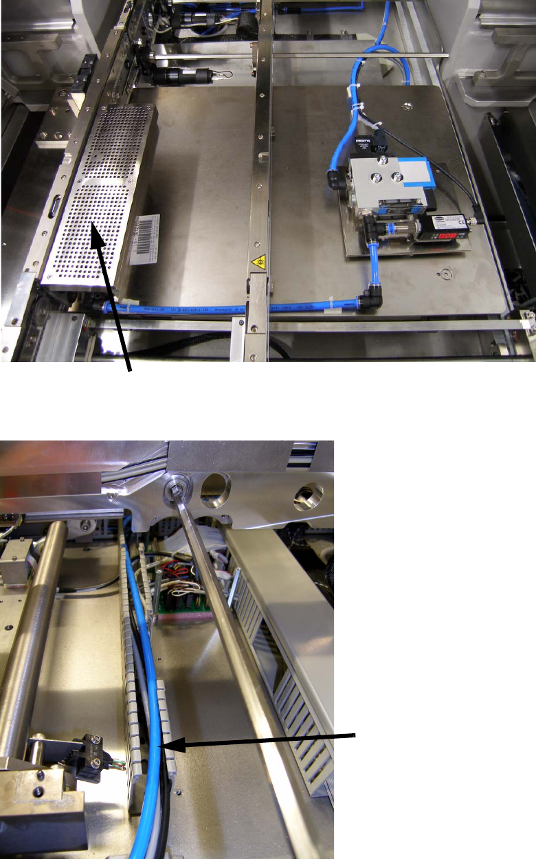
Hose- and cable layout
Special design 2 Assembly instructions Special design Vacuum tooling SIPLACE HS-60
10/2006 Edition
47
2
2
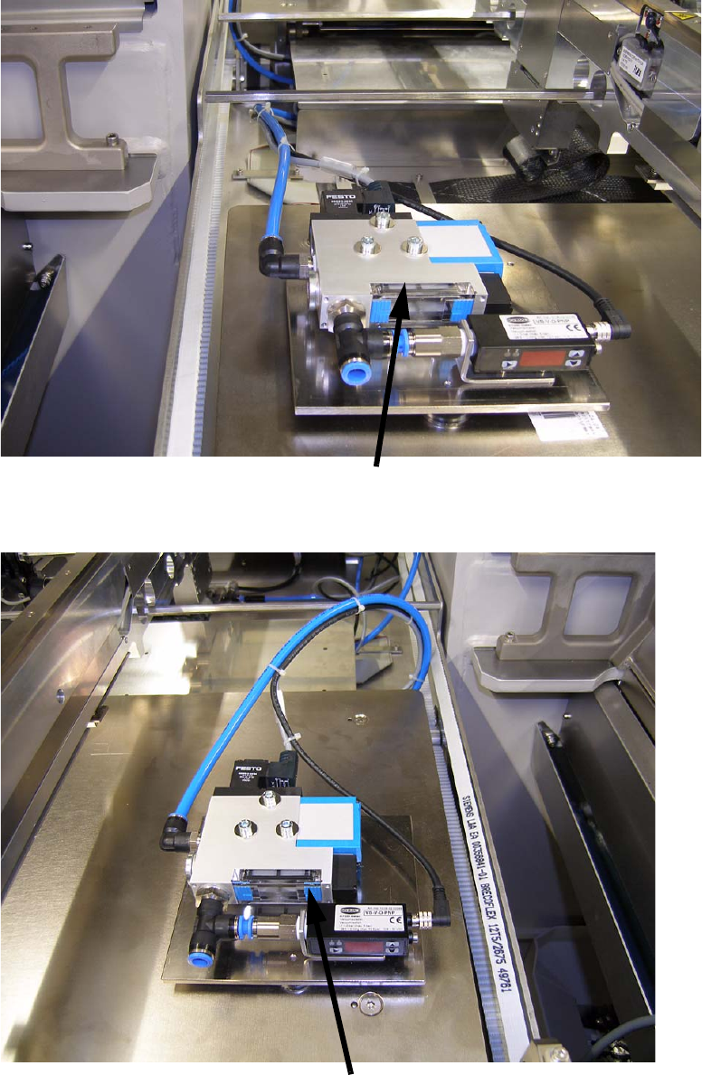
Vacuum generator PA1
Vacuum generator PA2
2 Assembly instructions Special design Vacuum tooling SIPLACE HS-60 Special design
10/2006 Edition
48
2
2
2.8.5 Running of the hoses and cables, pneumatic diagram
2.8.5.1 Running of the hoses and cables
2
The hoses and cables have to be run, that the lifting table and the width adjustment are not con-
stricted. The cables should not rub on any moving part of the machine. 2
2
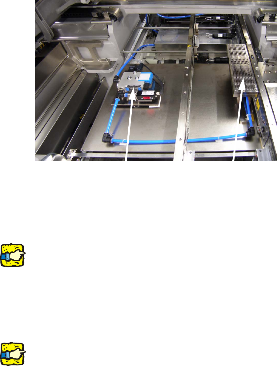
The hose from the maintenance unit, at least a PUN 8(single conveyor) or PUN 10 (dual con-
veyor), has to be run through the machine pedestal to the conversion board. There the hose
branch to two (single conveyor) or four (dual conveyor) hoses. The hose reduces from the branch
to PUN 8 and runs to the vacuum devices. From the vacuum devices a PUN 8 runs to every va-
cuum tooling. 2
2
2
The hoses at the lifting table should not rub on any of the moving parts. 2
2
2
Vacuum tooling
Vacuum generator