IPS adjustment on the modules.pdf - 第14页
E dition 1 .0 IPS Adjustment for V arious H ead T ypes on the Module < H24 head > FK - 9F50 - 74 -0E 1-2 FUJI C ORPORA TION Prepa rat ion o n the m odul e 1. R emove the covers . 2. Attach t he jigs (2AG KNJ0 01500…
Edition 1.0 IPS Adjustment for Various Head Types on the Module
<H24 head>
FK-9F50-74-0E 1-1 FUJI CORPORATION
Chapter 1- H24 head IPS adjustment
IPS Camera Position Adjustment, Current Value
(Grayscale Value) Adjustment and Area Check on the
Machine
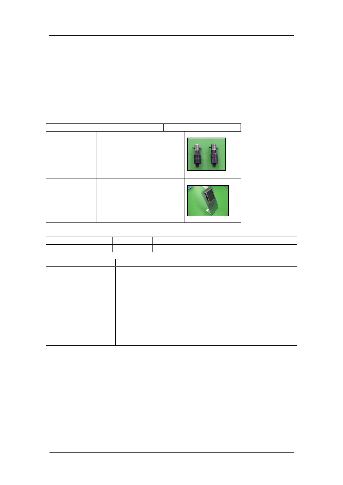
Requir e d Jigs
Drawing No.
Name
Qty
Photo
2AGKNJ001500
H24 IPS cam er a
resolution
measurement jig
2
2AGTHJ004802
IPS Monitor Jig
1
Required softw ar e
Name
Drawing No.
Notes
MotionAdjustmentTool
None
Inst al l fro m the NXT application C D-ROM
Inspection item
Tolerance
LED current adjustm ent
Grayscale value GR = 120~160, GL =120~160 (adjust current
value so GR & GL gray scale
values are greater than 95 & less
than 250. Target: 120
CURRENT value: 24 m A or less
Camera resolution
check
L: X = 92~108
L: Z = 92~108
Center val ue
R: Xs = 380~400
(Target: 390) , Zp = 235~255 (Target: 245)
L: Xp = 80~100
(Target: 90
)
, Zp = 237~253 (Target: 245)
Tilt
R: dX = 0~6 (Target: 0), dZ = 0~9 (Target: 0)
L: dX = 0~6
(Target: 0), dZ = 0~9 (Target: 0)
CONFIDENTIAL
Edition 1.0 IPS Adjustment for Various Head Types on the Module
<H24 head>
FK-9F50-74-0E 1-2 FUJI CORPORATION
Preparation on the module
1. Remove the covers.
2. Attach the jigs (2AGKNJ001500*) to holders B and X on t he head.
3. To adjust the IPS camera position, it is necessary to move the R-axis to the MT reset
position. The procedure is explained below.
4. Attach the head to t he module and t ur n t he base pow er O N.
5. After the machine wakes up, push the start button and then push the cycle stop button
immediately. After that, check that the R-axis h as been moved to the MT reset position.
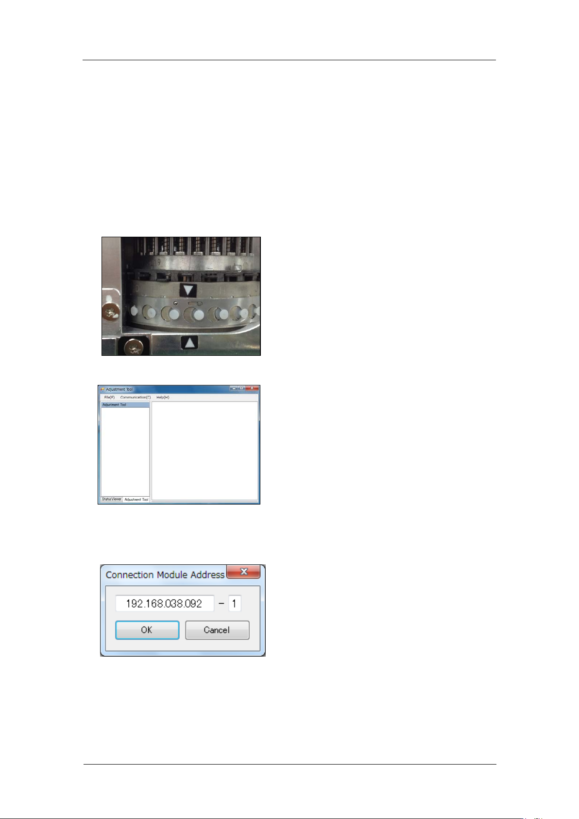
6. Check the servo count er on the modu le using the Motion Adjust ment Tool.
7. Startup MotionAjustmentTool.
8. Enter the IP address of the base and t he module number, and then click [Connect].
CONFIDENTIAL
Edition 1.0 IPS Adjustment for Various Head Types on the Module
<H24 head>
FK-9F50-74-0E 1-3 FUJI CORPORATION
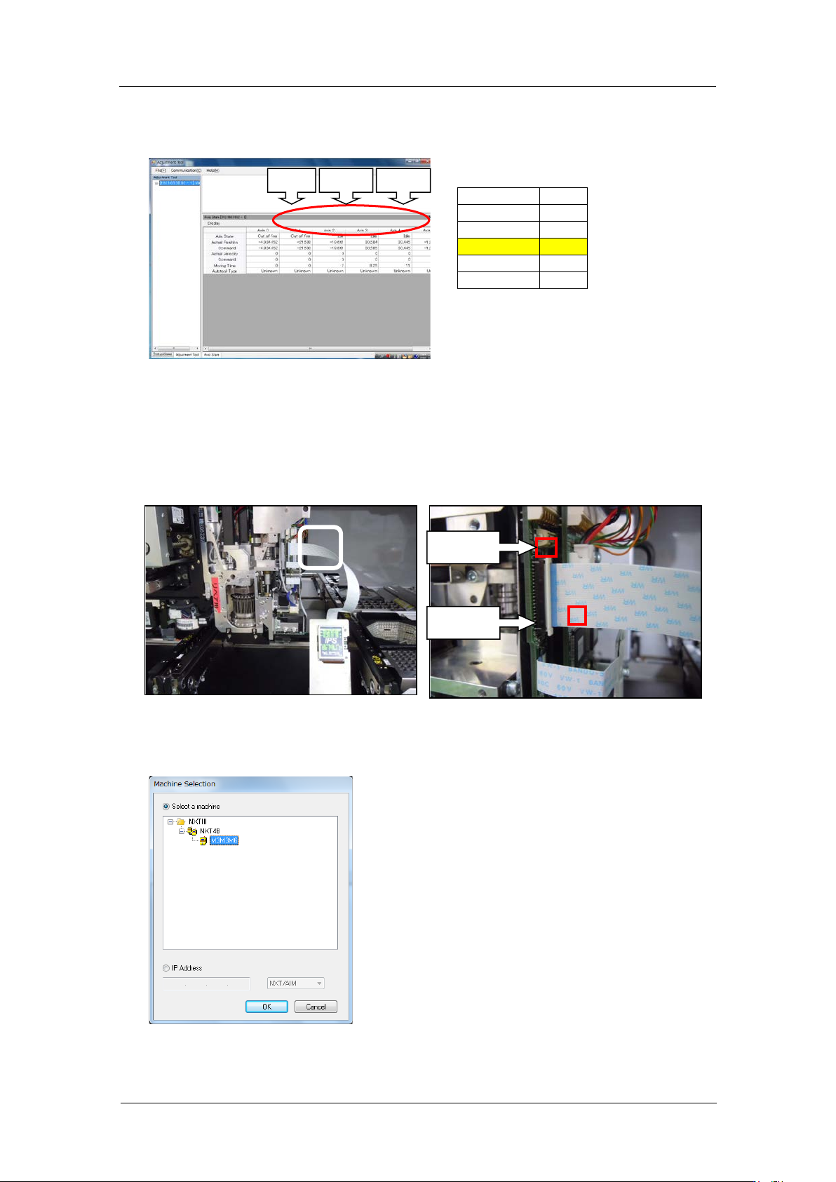
9. After communication, the current servo count of each axis is displayed. The Axis 3 is
the R-axis servo count er. Record this val ue. ( Re ference value : 30000 ± 3000 pulses)
10. Disconnect communication from Motion Adjustment Tool.
11. Press the POWER button t o s et t he mod ul e to sleep and turn OFF t he head pow er.
12. Attach the IPS monitor jig to the head. When connecting the harness, make sure the
blue side of the harness tip is facing the left as shown in the photo below. In addition,
be careful w ith the lock claw s inc e it is ea sy to break.
13. Press the POWER button to wake the module.
14. Open Equipment Check, select t he machine, and then clic k [O K].
Axi s map
Axis 0
Y
Axis 1
X
Axis 2
Z
Axis 3
R
Axis 4
Q
Axis 5
XS
Lock claw
Lock claw
Z-axis
R-axis
Q-axis
CONFIDENTIAL