IPS adjustment on the modules.pdf - 第42页
E dition 1 .0 IPS Adjustment for V arious H ead T ypes on the Module <H24G/H24 S/H24A > FK - 9F50 - 74 -0E 2-8 FUJI CORPORA TION Adjusting the Curr ent V alue (Gr a y s cale V alue ) : Adjustment 2 1. Press the upp…
Edition 1.0 IPS Adjustment for Various Head Types on the Module
<H24G/H24S/H24A>
FK-9F50-74-0E 2-7 FUJI CORPORATION
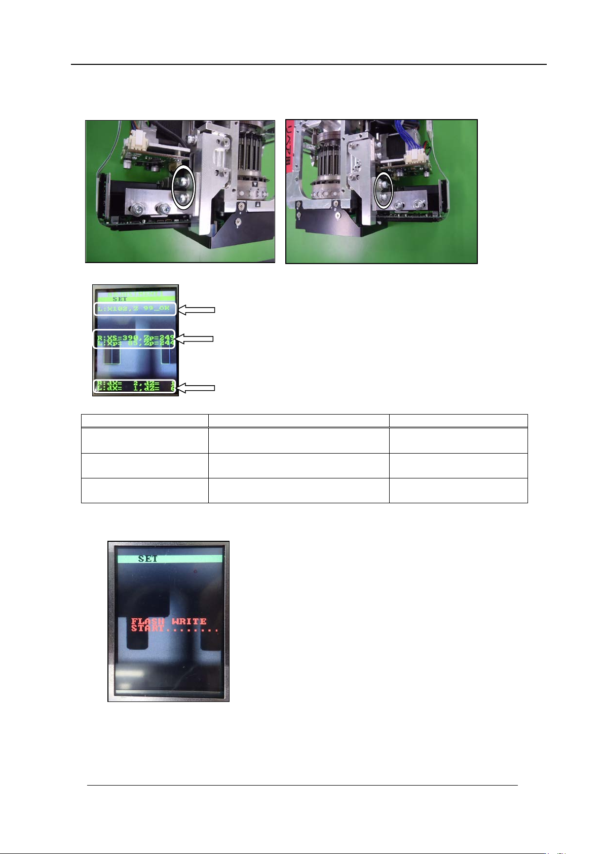
3. Use the bolts below to adjust the camera position so that the center value, resolution
and tilt are al l w ithin t olerance.
Inspection item
Tolerance
Target value
Camera resolution
L: X = 94~ 110
L: Z = 94~110
Same as tolerance
Center val ue
R: Xs = 380~4 00, Zp = 235~255
L: Xp = 80~ 100, Zp = 23 5~255
R: Xs = 390, Zp = 245
L: Xp = 90, Zp = 245
Tilt
R: dX = 0~6, dZ = 0~ 9
L: dX = 0~ 6, dZ = 0~ 9
R: dX = 0, dZ = 0
L: dX = 0, dZ = 0
4. If the results are w ithi n tolerance, pr ess the lower button t o save the sett ings.
5. Once savin g the setting s, r em ove the jig noz zles (2AGKNJ001500).
Resolution
Center val ue
Tilt
CONFIDENTIAL
Edition 1.0 IPS Adjustment for Various Head Types on the Module
<H24G/H24S/H24A>
FK-9F50-74-0E 2-8 FUJI CORPORATION
Adjusting the Current Value (Gr ayscale Value): Adjustment 2
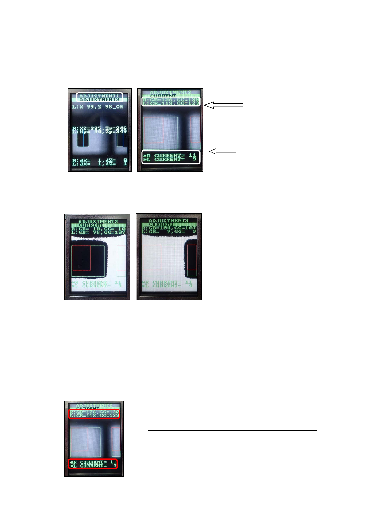
1. Press the upper button to change to [ADJUSTMENT 2] mode from [Adjustment 1].
Press the low er but t on t o display t he c ur rent values .
2. Press the upper and lower buttons s i m ultaneously t o rev er se the LCD contrast ,
Block the right-hand glass and check there is no effect on the left-hand area. Block the
left-hand glass and check there is no effect on the right-hand area. Attach the dia m et er
0.2 mm noz zle and check that the image is complet ely white.
3. Press the upper and lower buttons simultaneously to set the LCD contrast back to
normal.
4. Rotate the R-axis through one full rotation and confirm that there is no position where
the variation in the grayscale values (R:GB and L:GB) is extreme. If the grayscale
value is too big, check the fluorescent status. If it is dirty, clean or replace it as
necessary.
5. Rotate the R-axis by hand to find the positions where the grayscale values (R:GB and
L : GB) are maximized and minimized. Check that the minimum and maximum
grayscale v alues are within the tolerance of 140~160 (target: 150).
6. Also check that the current v alue is 24 m A or less.
Tolerance
Target
R
:
GB , L
:
GB (Gray value)
140~160
150
CURRENT
24mA or less
Grayscale
values
Current
values
CONFIDENTIAL
Edition 1.0 IPS Adjustment for Various Head Types on the Module
<H24G/H24S/H24A>
FK-9F50-74-0E 2-9 FUJI CORPORATION
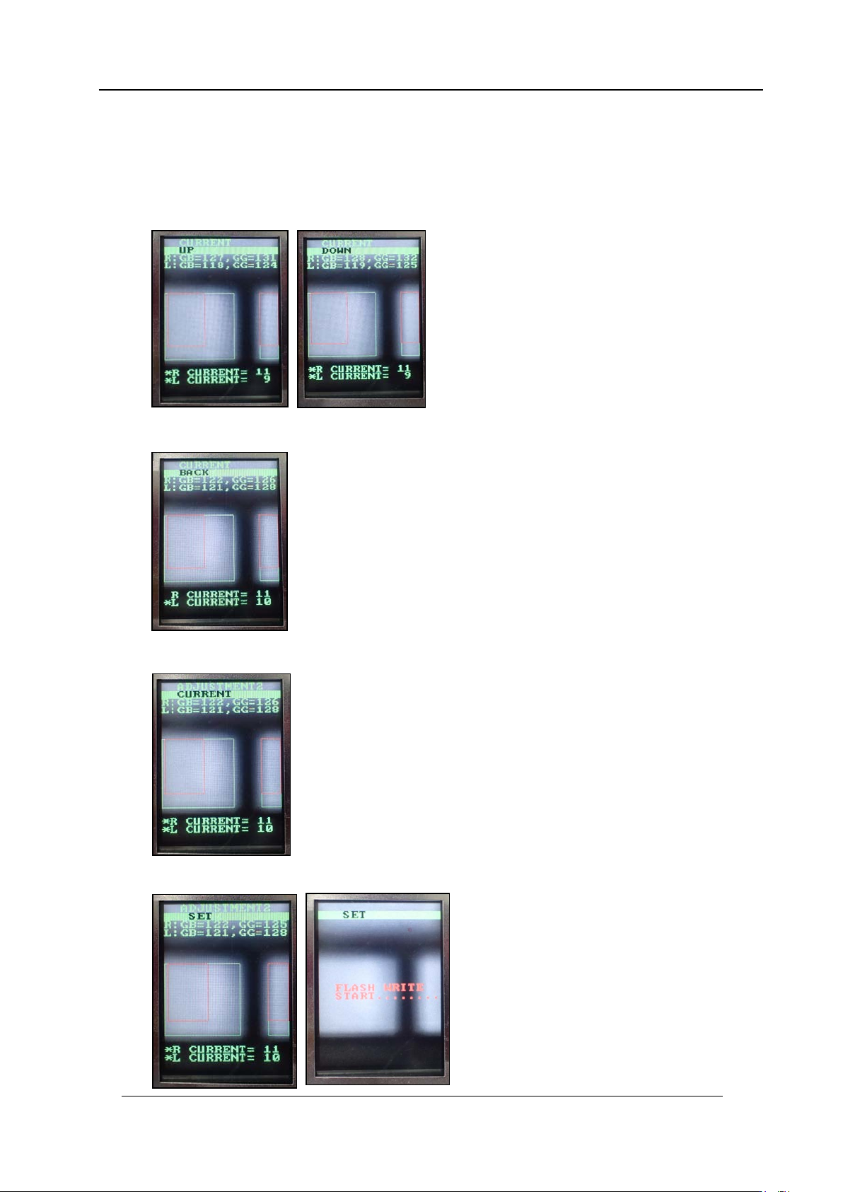
If the grayscale values are not w ithin the target val ues, adjust the m as shown bel ow.
7. Press the lower button to display “CURRENT UP” or “CURRENT DOWN”. When
raising the value, display “CURRENT UP” and press the lower button to adjust the
value. When lowering the value, display “CURRENT DOWN” and press the lower
button to adj ust the value.
8. Once the value is within the tolerance, press the upper button to display “CURRENT
BACK”.
9. Press the low er but t on t o return to “ADJUST M ENT 2 CURREN T” .
10. Press the upper button to display “ADJUSTMENT 2 SET” and then press the lower
button to save the sett ings.
CONFIDENTIAL