IPS adjustment on the modules.pdf - 第19页
E dition 1 .0 IPS Adjustment for V arious H ead T ypes on the Module < H24 head > FK - 9F50 - 74 -0E 1-7 FUJI C ORPORA TION Adjusting t he Ca m e r a I nstalla tion P osi tion 1. Check that t he R - axis is at the …
Edition 1.0 IPS Adjustment for Various Head Types on the Module
<H24 head>
FK-9F50-74-0E 1-6 FUJI CORPORATION
Configur a t ion Settings
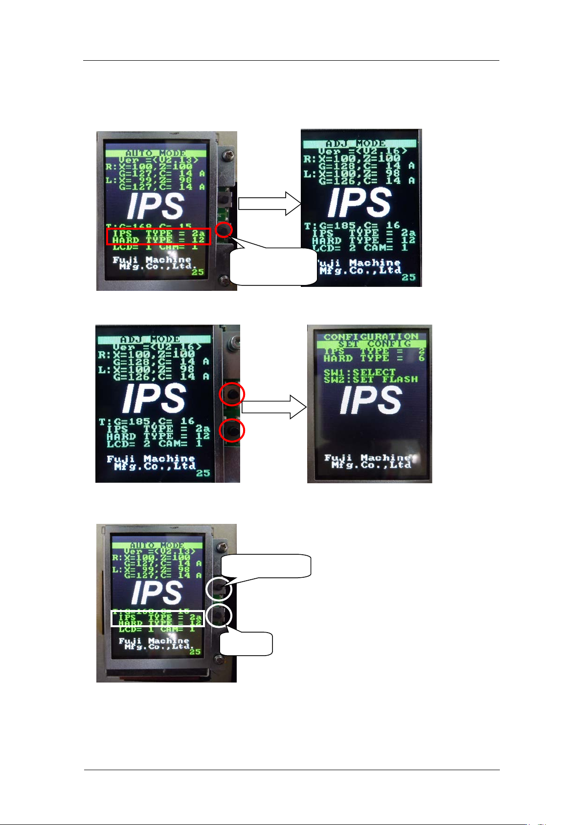
1. Firstly, check that the “IPS TYPE” is set to 2a and “HARD TYPE” is set to 12 on the
LCD screen. If NOT, hold the lower b ut ton and change the screen to “ADJ M O DE”.
2. If they are not set like above, press both of upper and lower buttons to change the
screen to “CONFIGURATION”.
3. Set the “IPS TYPE” to 2a and the “HARD TYPE” to 12 with the upper button. Pres s t he
lower button t o save the s et ting.
4. If you chang ed the settin gs, reboot t he bas e.
Select [TYPE]
Save
Hold the lower
button.
CONFIDENTIAL
Edition 1.0 IPS Adjustment for Various Head Types on the Module
<H24 head>
FK-9F50-74-0E 1-7 FUJI CORPORATION
Adjusting t he Ca m e ra Installation Position
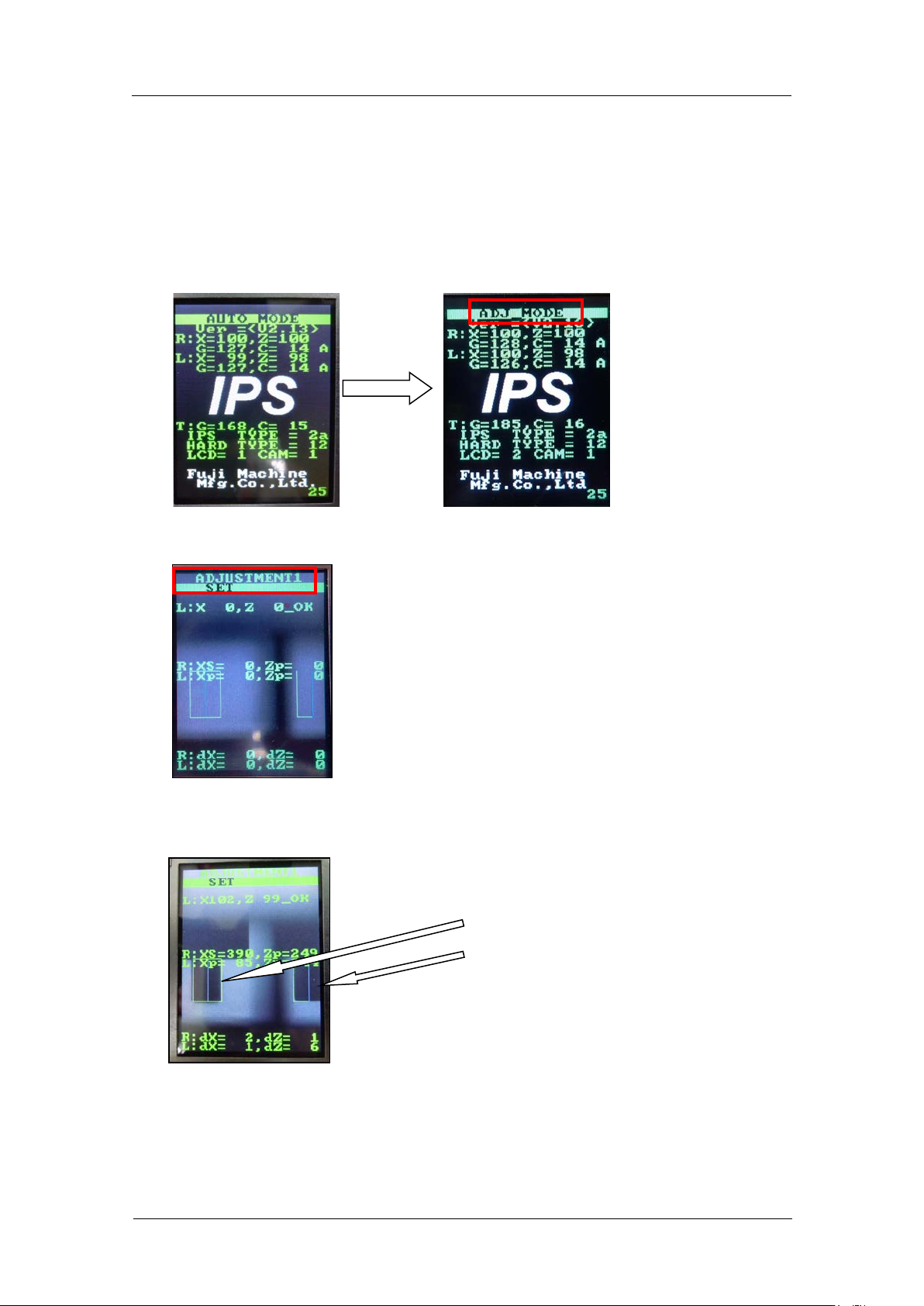
1. Check that the R-axis is at the calibration data position (Reference value:30000 ±
3000 pulses) .
Note: Be sure to keep this positi on while a djusting the IPS cam er a posit i on.
2. Press and hold the low er button for a few s econds to shift to “ADJ MODE”.
3. Press the lower button to shift to “ADJUSTMENT 1” and LED lamp flashes.
4. Adjus t t he position of the camera so that the jigs on the B and X holders match up with
the green frames on the screen.
The jigs match the
green frames on the
screen.
CONFIDENTIAL
Edition 1.0 IPS Adjustment for Various Head Types on the Module
<H24 head>
FK-9F50-74-0E 1-8
FUJI CORPORATION
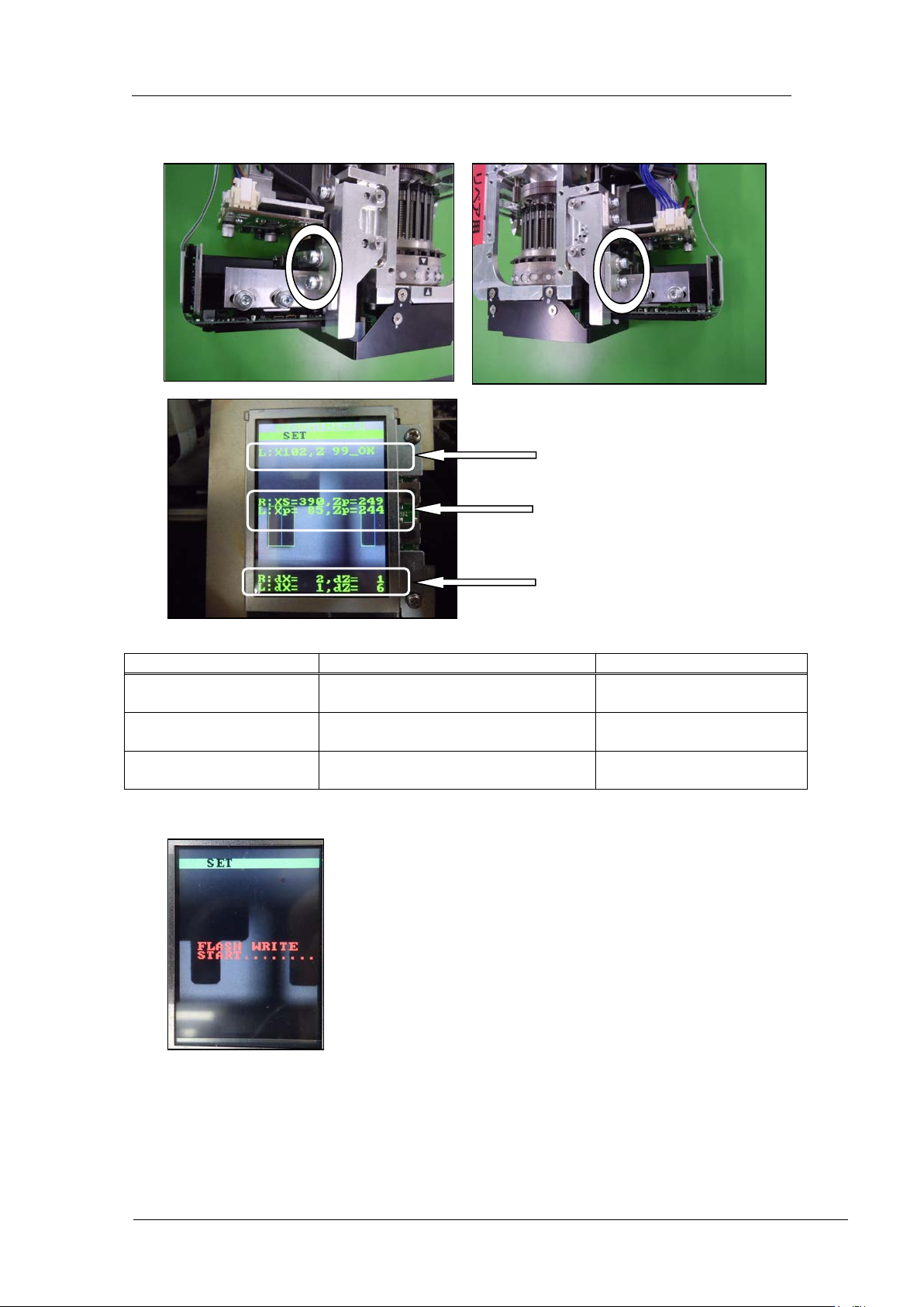
5. Use the bolts below to adjust the camera position so that the center value, resolution
and tilt are al l w ithin t olerance.
Inspection item
Tolerance
Target value
Camera resolution
L: X = 92~ 108
L: Z = 92~108
Same as tolerance
Center val ue
R: Xs = 380~400, Zp = 235~255
L: Xp = 80~ 100, Zp = 237~253
R: Xs = 390, Zp = 245
L: Xp = 90, Zp = 245
Tilt
R: dX = 0~6, dZ = 0~ 9
L: dX = 0~ 6, dZ = 0~9
R: dX = 0, dZ = 0
L: dX = 0, dZ = 0
6. If the results are w ithi n tolerance, pr ess the lower button t o save the sett ings.
7. Once savin g the setting s, r em ove the jig nozzles (2AGKNJ001500).
Resolution
Center val ue
Tilt
CONFIDENTIAL